DarkStar
Well-known member
This post has been removed.


It is frightfully common that when the wire gauge is too big to fit in the terminal lug, the installer shaves the strands to reduce the effective diameter of the wire. It's not always a big deal but it shouldn't be necessary at all. That said, that is easily the worst job of it I have ever seen and the person who built (and the person who presumably inspected) that unit should be on the verge of losing their jobs. Are these things UL listed? If so that's just inexcusable.chris1howell said:Are those wires touching? Hope the breaker trips beacuse there are no fuses.
Smidge204 said:Messy wiring and protoboards make sense for very low production where it's not cost effective to more fully integrate the components. But the work in those photos still seem extra shoddy, like the kind of thing some guy would throw together in his garage over a weekend
They are not "throwing together" EVSEs - they are building them. World of difference there! :lol:chris1howell said:The guys throwing EVSEs together in garages over the weekends are doing really nice jobs. See the thread EVSEs built with OpenEVSE boards...http://www.mynissanleaf.com/viewtopic.php?f=26&t=7945
Because you'll never know when you need TWO power supplies... I really wish this surprised me...
") . At least the case and J-1772 cable/connector and perhaps 1 of these power supplies (although the end result would probably come out better if you just used one of your advanced power supply's) are reusable and the J-1772 assembly is still the most expensive part of the project.
. At least the case and J-1772 cable/connector and perhaps 1 of these power supplies (although the end result would probably come out better if you just used one of your advanced power supply's) are reusable and the J-1772 assembly is still the most expensive part of the project.chris1howell said:mitch672 you are correct, there is a ton of space. I should be able to lay things out really well. The only thing I am going to use is the cables and case. I will use the OpenEVSE Advanced Power Supply to simplify the EVSE and add additional safety features including stuck relay detection and ground monitoring.
Use Case
Use J1772 cable (Yazaki 30A)
Use AC power cable
Add 30A fuses
Replace 2x power supplies with OpenEVSE Advanced Power Supply
Replace LCD with Adafruit RGB LCD
Add OpenEVSE board set to 30A
Add CR Magtnetics 8420-1000-G CT coil for GFCI
Add 30A mechanical Relay
When I am finished, this EVSE should be much safer and a lot more reliable.
davewill said:Of course, if those guys really wanted to put out a quality unit, they could always adopt the OpenEVSE design themselves...
Yeah, I can just imagine the hash they'd make trying to customize the firmware...and they'd probably screw up the GPL requirements, too.z0ner said:That would require competence.
Of course, if those guys really wanted to put out a quality unit, they could always adopt the OpenEVSE design themselves...
Boards are available for sale and the hardware/firmware is all out there Open Source so there is nothing stopping them.
That would require competence.
Two power supplies... Maybe one for -12v Pilot generation?
-Phil
chris1howell said:


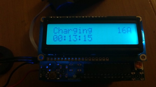


chris1howell said:There was no external indication of status on the EVCA EVSE (except LCD), so I added a RBG LCD. From a distance it is easy to see what is going on... Green "Ready but not connected", Yellow "Waiting for EV", Blue "Charging" and Red indicates an Error.
Enter your email address to join: