OpenEVSE - Open Source Charging Station

My Nissan Leaf Forum

Help Support My Nissan Leaf Forum:

This site may earn a commission from merchant affiliate links, including eBay, Amazon, and others.
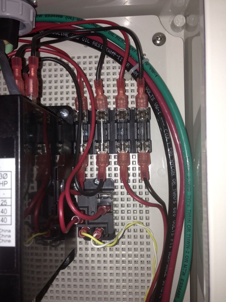
Can be seen in my 75A OpenEVSE as well, a 12V relay controls the contactors 240V coil... See picture below

My build: http://code.google.com/p/open-evse/wiki/75AOpenEVSE" onclick="window.open(this.href);return false;

null-4.jpg
 
I believe that the 12v DC from the OpenEVSE is used to close
a small 12v-actuated relay, similar to 30 amp relay in the
30-amp EVSEs, but probably smaller.

This small "control" relay closes contacts to provide power to
the BIG relay, to activate it.

Does the big relay accept both 120v and 240v AC as an actuation
voltage, or does the EVSE operate on 240v only?

What are the 4 fuse-like parts, surge protection?
 
garygid said:
What are the 4 fuse-like parts, surge protection?

The two fuses on the right are 120/240v that goes to the 12v power supply that powers the small relay to power the big 75amp relay, and also the Arduino.

The two fuses on the left are 120/240v to the big 75amp relay. The black conductor (second from the left in the above pic) is not switched, the the furthest left one is switched by the 12v relay.

The white/yellow twisted conductors are power for the 12v relay.

Heck, there's still an unused switched 120v line coming out of the 12v relay. Quick, must find something to power.
 
TonyWilliams said:
garygid said:
What are the 4 fuse-like parts, surge protection?

The two fuses on the right are 120/240v that goes to the 12v power supply that powers the small relay to power the big 75amp relay, and also the Arduino.

The two fuses on the left are 120/240v to the big 75amp relay. The black conductor (second from the left in the above pic) is not switched, the the furthest left one is switched by the 12v relay.

The white/yellow twisted conductors are power for the 12v relay.

Heck, there's still an unused switched 120v line coming out of the 12v relay. Quick, must find something to power.

Mostly right, except the contactor coil only operates on 240V (.1 amps, if you are curious, I was)
If you use a model with a 120V coil (they do make them), you would technically have to run a neutral to the EVSE.. I only have 2 hots and the ground. I fused the 240V coil circuit seperatly from the 240V feeding the 12VDC power supply running the OpenEVSE, technically you don't need to do this, but I wanted to measure the current on the coil only, and this was the easiest way to wire it. The contactor has (2) 1/4" male tabs on each input leg, so it was very easy to get the AC inputs to the fuse holders.

Gary, the "4 fuse like devices" are fuses :) 2A slow blow on the contactor coil circuit, and 1A fast blow on the 12VDC power supply inputs. The 75A EVSE only runs on 240V, not much point in making it portable, given you need to feed it with #3 gauge wire on a 100A circuit breaker :). The main EVSE is not fused, the circuit breaker protects the main wiring, and the final device will be hard wired (100A plugs and outlets tend to get expensive and are not needed). I plan to have a 8" box above the unit, leaving a small "service loop" in the box for extra wire, and the 1" PVC from that box to the NEMA enclosure won't have the PVC pipes glued together, so I can take it off the wall to work on it.
 
Pictures of my 2013 Chevy Volt portable EVSE after gutting and replacing with Open EVSE components. Many thanks to GlennD, he guided me through the process and then last night wired everything up, programmed the chip and tested the unit on 120V. I still need to add an L6-20 male connector to the power pigtail so I can use all the 240V connectors I have left from from when I owned a Leaf.

http://www.flickr.com/photos/8465388@N06/8243569687/in/photostream/

http://www.flickr.com/photos/8465388@N06/8244637630/in/photostream/
 
Adrian said:
Pictures of my 2013 Chevy Volt portable EVSE after gutting and replacing with Open EVSE components. Many thanks to GlennD, he guided me through the process and then last night wired everything up, programmed the chip and tested the unit on 120V. I still need to add an L6-20 male connector to the power pigtail so I can use all the 240V connectors I have left from from when I owned a Leaf.

http://www.flickr.com/photos/8465388@N06/8243569687/in/photostream/

http://www.flickr.com/photos/8465388@N06/8244637630/in/photostream/

Holy smokes!! You're going to put Phil out of business! Have you no shame?

:mrgreen:
 
Adrian,
Nice work, Thanks for the pictures.

It looks like the EVSE case was not that difficult to open?

Using the newer OpenEVSE Plus, which is smaller, the
"Gut-up-Grade" might even be easier.

Does the Volt charge at a max of 16 amps?

Does this upgrade primarily give you 120v /240v operation,
or does it also allow multiple charge rates.

What were the original Volt EVSE specifications, 120v 12 amps?

With this upgrade you have 240v 16 amps max?

So, you upgraded the input cable, and the J1772 cable to
handle the 16 amps?

Mucho cool.
Proud of you, Gary
 
Gary, the Volt EVSE wires are tiny (no more than 14GA, some bits may even be 16GA!). While they can probably handle 16A for a short period of time, 12A is the recommended maximum current.
 
garygid said:
Adrian,
Nice work, Thanks for the pictures.

It looks like the EVSE case was not that difficult to open?

Using the newer OpenEVSE Plus, which is smaller, the
"Gut-up-Grade" might even be easier.

Does the Volt charge at a max of 16 amps?

Does this upgrade primarily give you 120v /240v operation,
or does it also allow multiple charge rates.

What were the original Volt EVSE specifications, 120v 12 amps?

With this upgrade you have 240v 16 amps max?

So, you upgraded the input cable, and the J1772 cable to
handle the 16 amps?

Mucho cool.
Proud of you, Gary

Thanks Gary!

The 2013 Volt oem 120V portable charger has 6 secure torx screws. It took 5 minutes to open. It can charge at 8 or 12A.

Yes, Volt will charge at max 16A on 240V.

This upgrade will continue to provide 120V at 8 or 12A (user selectable in car, unchanged from oem), and now the option of 240V at 15A. I picked 15A because I found that to be the max current for 3 conductor 14 awg cable my Volt EVSE has. I kept the original J1772 connector and cable due to portability (fits nicely in my trunk) and cost ($0). I upgraded the input cable. I hope the J1772 handle can handle this increase as it is not stamped with the information so I can't verify that. I will monitor using an IR thermometer the first few times I use it on 240V.
 
TonyWilliams said:
Adrian said:
Pictures of my 2013 Chevy Volt portable EVSE after gutting and replacing with Open EVSE components. Many thanks to GlennD, he guided me through the process and then last night wired everything up, programmed the chip and tested the unit on 120V. I still need to add an L6-20 male connector to the power pigtail so I can use all the 240V connectors I have left from from when I owned a Leaf.

http://www.flickr.com/photos/8465388@N06/8243569687/in/photostream/

http://www.flickr.com/photos/8465388@N06/8244637630/in/photostream/

Holy smokes!! You're going to put Phil out of business! Have you no shame?

:mrgreen:

I would have gladly paid Phil instead, but his upgrade of the 2013 Volt EVSE eliminates 120V charging capability which was a deal breaker for me.
 
Good job Adrian!

By the way, regarding the Pull-away functionality people are adding with the anderson connectors, I recommend you avoid this. This adds a point of failure, as I've seen many of these connectors fail in the field. When/if they do, it could result in a fire. This is especially a concern at much over 20A. (Such as a 30A EVSE)

I recommend you put a small faston connector on the pilot, and then secure it in such a way that it pulls out as soon as there is any movement. I suspect many people will not be mounting the EVSE to the wall that securely anyway. (if at all in the case of portable!) It would have to be such that it will stay on the wall in the event enough force is subjected to the cable to pull it from the gland.

Most EVSE designs just use the "short pilot" wire trick. If you are using crimp-on, or screw-clamp connectors, that's sufficient pull out protection. If it can pull out of the gland, it will pull out of whatever else holds it.

-Phil
 
Adrian said:
Pictures of my 2013 Chevy Volt portable EVSE after gutting and replacing with Open EVSE components. Many thanks to GlennD, he guided me through the process and then last night wired everything up, programmed the chip and tested the unit on 120V. I still need to add an L6-20 male connector to the power pigtail so I can use all the 240V connectors I have left from from when I owned a Leaf.
Nicely done Adrian! I did something similar back in August using a 2012 Volt portable EVSE and one of 3 integrated OpenEVSE boards (the power supply and relays were put on a single very small board) that Chris made. The older Voltec portable's were sealed and so had to be pried open and glued back unlike the current 2013 ones.
 
I am not fond of power poles and it is nice to have an expert back up my experiences.

There is a lot of clutter in the finished. photo of the Volt EVSE. I hate seeing it but its hard to work without making a mess.

Adrian managed a first class job of making the parts fit. Greg's board and a power supply were a whole lot less than Chris's latest and greatest. Chris is a genius at making tiny working surface mount stuff. Given a choice I like the discrete parts better.

Unless you have access to a hot air system its use it till it breaks and buy a new one. A hot plate can flow solder parts and turn out a professional product but its take it or leave it if it breaks.
 
Ingineer said:
Good job Adrian!

By the way, regarding the Pull-away functionality people are adding with the anderson connectors, I recommend you avoid this. This adds a point of failure, as I've seen many of these connectors fail in the field. When/if they do, it could result in a fire. This is especially a concern at much over 20A. (Such as a 30A EVSE)

I recommend you put a small faston connector on the pilot, and then secure it in such a way that it pulls out as soon as there is any movement. I suspect many people will not be mounting the EVSE to the wall that securely anyway. (if at all in the case of portable!) It would have to be such that it will stay on the wall in the event enough force is subjected to the cable to pull it from the gland.

Most EVSE designs just use the "short pilot" wire trick. If you are using crimp-on, or screw-clamp connectors, that's sufficient pull out protection. If it can pull out of the gland, it will pull out of whatever else holds it.

-Phil

Phil, thank you for the recommendations. I will follow them.
 
What is the purpose of the CT? And specifically, does it go on the input wires (before the relay) or on the J1772 output wires?

In this schematic, the CT is before the relay: http://code.google.com/p/open-evse/wiki/EVSE_Example75A" onclick="window.open(this.href);return false;

In this schematic, the CT is after the relay: http://open-evse.googlecode.com/files/EVSEwAdvanced_Power_supply.pdf" onclick="window.open(this.href);return false;

I assume the board with the Advanced Power Supply is somehow different, and that's why the placement of the CT has moved, but I want to understand it a little more.

Harry
 
MashedPotato said:
What is the purpose of the CT? And specifically, does it go on the input wires (before the relay) or on the J1772 output wires?

In this schematic, the CT is before the relay: http://code.google.com/p/open-evse/wiki/EVSE_Example75A" onclick="window.open(this.href);return false;

In this schematic, the CT is after the relay: http://open-evse.googlecode.com/files/EVSEwAdvanced_Power_supply.pdf" onclick="window.open(this.href);return false;

I assume the board with the Advanced Power Supply is somehow different, and that's why the placement of the CT has moved, but I want to understand it a little more.

Harry

The Current Transformer is to measure for an inbalance of current going in vs. current going out or in other words a ground fault. The advanced power supply and OpenEVSE Plus boards test both AC lines for several safety checks by sending a small current to ground. The CT must be placed on the J1772 cable side of the relay to avoid false trips during the testing of the AC lines.
 
Thank you for the explanation. I thought understanding the CT would help me figure out the problem(s) I'm having with Open EVSE.

It powers up, goes through the initial tests and gets to the "ready L2 16a" state (the default was set to 16a at the workshop) and the car charges with it normally. However, the select button doesn't do anything.

I brought it inside to work on it, wiring a standard 110v plug with ground and it showed "L1 12a" as expected. When ground is removed however, it displays "L2 16a", even though it's only L1. (I discovered this accidently, when ground was removed.) Is this an expected state when ground is removed?

Back to checking everything on the Adafruit to see why my select button isn't working...

Harry
 
The EVSE can use 2 different buttons and the proper one must be set. Originally it used a hardware switch to ground through a resistor. Someone wanted the switches on the display board to work so lincomatic figured that out.

It sounds like the wrong switch is selected. you can try pulling the analog pin next to the i2c pins to ground through a 2.2 k resistor.

I can reprogram your EVSE if you need it. I live in Anaheim near Disneyland.
 
Back
Top