OpenEVSE - Open Source Charging Station

My Nissan Leaf Forum

Help Support My Nissan Leaf Forum:

This site may earn a commission from merchant affiliate links, including eBay, Amazon, and others.
I'm having the same issue as Mashed Potato, and here I thought I fudged a solder joint.

I was thinking about buying a USB programmer but I'm not sure I should go through the time and expense if this will be my only foray into EVSE building.

GlennD, if your offer is extended to me I'd like to take you up on it.

Jeff
 
I am available for OpenEVSE reprogramming as well, if you are located in the Boston area.

I have built a few for Plug in Prius users, and did program & test an OpenEVSE V4.0 thruhole board for someone as well.
 
I'm in the process of making three of these in the Bay Area. I have learnt one or two things and will post them up when i'm done. I'm happy to help as I have plenty of electronics equipment (not machine shop) at home.

Cheers!
 
This thread provides a chance for members, experienced in building electronic devices, to share their expertise with other less-experienced members; I would like to see those members who are willing to help each other build an EVSE(s) post their wishes here and then PM each other on specifics.

That appears to be happening anyway so let's encourage it.
 
fotajoye said:
This thread provides a chance for members, experienced in building electronic devices, to share their expertise with other less-experienced members; I would like to see those members who are willing to help each other build an EVSE(s) post their wishes here and then PM each other on specifics.

Here's a good project that isn't an OpenEVSE, but uses many of the skills.

http://www.mynissanleaf.com/viewtopic.php?p=248883#p248883" onclick="window.open(this.href);return false;
 
I am willing to help Orange County or Leaf range people. I am a radio tech for the City of Long Beach so I have lots of hands on experience. I have a fully equipped shop. I make a fair wage from the city so I am not trying to get rich at your expense.

I wired Ardrian's EVSE after he mounted the parts. He did a superb job. I really want to help.

So far I have constructed a EVSE with parts from Chris, A test unit from scratch using an Evil Mad Scientist proto board, A portable unit using Chris's original 2nd generation with an added GFCI circuit, My home unit with Barbouri"s ver 3 blank board, A unit from scratch using a proto board, an Adafruit display, and a Uno, A unit for work using Chris's shield, an Adafruit display, and a Uno.

Its not hard on the hardware side and the excellent firmware is in the public domain. I have used the hard work of Chris Howell and Sam Lin ( lincomatic). I have no software skills and its great others do.
 
TonyWilliams said:
Here's a good project that isn't an OpenEVSE, but uses many of the skills.

http://www.mynissanleaf.com/viewtopic.php?p=248883#p248883" onclick="window.open(this.href);return false;

A little suggestion:

I always try to "tin" the ends of stripped wires when possible to clean up the loose strands, tie all the strands together and assure I have a good clamping surface.
 
Maybe one of the folks with the capability to reflash the OpenEVSE Plus
could attend our Gathering this Saturday in Santa Ana, and bring their
programming "tools" with them.

I would like to get the same ability on my Windows Vista Laptop.

Chris was going to send me a zip file of all the necessary components,
including the libraries and source code for the OpenEVSE Plus, but
perhaps he has been too busy to get it together.

In any case, I will bring a flash drive, my laptop, and a programmer.

See you Saturday, about 1.4 days from... Now!
 
I'm having real difficulty in setting up the source to be able to compile out of box with RBG LCD and button menu. I want to make further enhancements but i can't get it started.

If someone can create a step by step tutorial to compile from scratch, it would be highly appreciated!

One additional question: Do you put L1/L2 connection sense before or after the relay. I saw somewhere that you put it after the relay but it doesn't make sense to me. I thought it should go before. Please confirm.

Edit: got it compiling now. Needed the Rgb library and missed the note regarding the timer include files.
 
goldserve said:
One additional question: Do you put L1/L2 connection sense before or after the relay. I saw somewhere that you put it after the relay but it doesn't make sense to me. I thought it should go before. Please confirm.

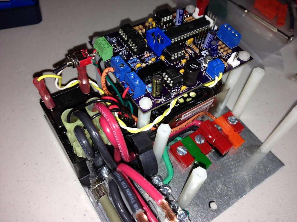
After. It's used for "stuck relay detection" as well. It connects along with the J-1772 wiring connections. Keep in mind, if you have a 120V GFCI you are plugging into, you will need to turn off the "stuck relay", "ground check" and "auto detect" on the L1/L2 menu, as it sends a small current on the ground, and most residential GFCIs will trip if you leave the checks on. The ones I built using the thruhole OpenEVSE V4 boards, I put a small SPST switch on the "ground" input on the advanced PS, (so you can temporarily disconnect the circuit) not sure that can be done on Chris's new integrated design though.

Switch can be seen in this picture, upper left. It only switches the ground (so the 120V inputs can then not complete the circuit)

9F69BBF1-567B-4C38-A079-1357D1AA4883-2596-0000012B38B1ACA2.jpg
 
Gary, I would attend the meeting except for an 8-8:30 meeting with the appraiser for my refinance. I thought I gave you a configured CD.
 
Thanks for the explanation on the L1/L2 detection. I guess i could have figured this out if I looked at the code. I thought the detection would have happened before enabling the relay.

Anyways, why would you want to switch the GND to the detection?
 
goldserve said:
Thanks for the explanation on the L1/L2 detection. I guess i could have figured this out if I looked at the code. I thought the detection would have happened before enabling the relay.

Anyways, why would you want to switch the GND to the detection?

If you remove the ground on the L1/L2 detection circuit, it will not trip a standard GFCI, if that's what you happen to have where you need the OpenEVSE to work at the moment. The detection / check is not required to have it function, it's just quicker to flip a toggle switch than to change options on the menu, especially if it is a 1 time use scenario. Trust me, if all you have is a GFCI outlet and your in a rush, you will appreciate being able to disable the test quickly, so your GFCI doesn't trip.
 
Back from page 55 I'd like to follow up. After trying everything I could think of I sent the open EVSE board back to Chris who graciously tested it out and found the same issue I had with the chip not accepting a program. After replacing the board everything worked again as expected. It was simply infant failure of the chip.

Thanks again Chris for your help.
 
garygid said:
Now that you "got" it, maybe you can get it all into one
Folder (and sub-folders), and write the step-by-step, and
zip it all for the rest of us?
Thanks, Gary

Here, I wrote a quick write-up to summarize all my learnings from compiling the OpenEVSE firmware: http://sdrv.ms/UZ469G" onclick="window.open(this.href);return false;
 
Back
Top