OpenEVSE - Open Source Charging Station

My Nissan Leaf Forum

Help Support My Nissan Leaf Forum:

This site may earn a commission from merchant affiliate links, including eBay, Amazon, and others.
It's just a plain 6x6 ABS electrical box enclosure, $8 at Lowes.
But with the custom designed Graphics it changes the entire look
of the plain old grey plastic box.

http://www.lowes.com/pd_10029-1716-L5133709_0__?productId=3276255&Ntt=electrical+box+abs&pl=1&currentURL=%3FNtt%3Delectrical%2Bbox%2Babs&facetInfo=#specifications-tab" onclick="window.open(this.href);return false;
 
djjazzy,

I agree with pachakutek, you did a great job on graphics and box design.

My OpenEVSE is also done, installed and working great, but looks so drab by comparison.

What did you use to apply graphics? Are those decals, silk-screen print, or something else?

Bob
 
Photoshop was used to custom design the graphics. Then
just saved it as a jpeg and sent it to the 1 hour photo lab
at Walgreens. Made the actual print image 5 7/8" x 5 7/8"
on an 8 x 10 gloss finish.
 
I have lately been playing with Barbouri's Ver 4.2 boards. There seems to be two versions available from OHS Park. The one in the shared projects is slightly different than the one that you order as a single board. The DC to DC converter's have a different footprint. The shared projects one uses the smaller one like the 4.0 board but 15V instead of 12V. The earlier version has the 78L12 basing wrong. You have to bend the leads in the correct orientation.

The version 4 boards use a Max 5033 switching 5V regulator. This adds about twenty dollars to the project. The chip alone is 13.62 from Digikey. This seems to be a clean design but total overkill since the 5V drain is very low.

I have built up 2 boards using the NKA1215SC DC to DC supply. One was stock and one used a 78L05. The Max version drew 46Ma with a green display and 53Ma with a white screen. The 78L05 version drew 65Ma with a green display and 78Ma with a white screen. As expected the 78L05 runs cold to touch. This is with Greg's OpenEvse display ver 4.2

I realize that I am riding the coat tails of Greg's design but for me the cost difference is not worth the added expense. A few versions back when the DC to DC converter ran on 5V a more efficent regulator would make sense. Currently the DC to DC runs on 12V and it does not load the 5V at all.
 
GlennD said:
I realize that I am riding the coat tails of Greg's design but for me the cost difference is not worth the added expense. A few versions back when the DC to DC converter ran on 5V a more efficent regulator would make sense. Currently the DC to DC runs on 12V and it does not load the 5V at all.
Good to hear that you are experimenting with the 4.2 board.
I had four goals when building the DIY OpenEVSE boards from Chris Howell's original design.
(1) Make it simple for a hobbyist with basic soldering skills.
(2) Keep it compatible with existing software and hardware as possible while still allowing for experimentation and modification.
(3) Make it as energy efficient as possible, as many EVSE's are powered 24/7 .
(4) Make it as immune as possible from external power noise and surges, as several builders were having problems with this.

As a side benefit for me, it was a chance to experiment and learn more about switching regulator design and driving long signal lines (Pilot) in a hostile environment.

The current board version is 4.21 and has an optional 5th pin on the display header and the corrected 12v regulator IC3 mounted directly below IC2.
9492390296_5b3b9bd3ba.jpg

Greg C. (Barbouri)
 
Greg, I think noise is not a problem with your design. Its a good thing bypass caps are cheap! It seems to me Chris does not use enough caps and you go overboard. Really, 2 caps on the MID400 power buss less than 1/2 an inch away.

On Chris's plus diy board I always add a cap between pins 7 & 8 to bypass the processor power.


Both designs have worked fine for me. I do like some of the added caps but since they only cost a nickle I fill all of your spaces.
 
It was pretty easy to sub the 78l05 for the switching regulator. On other boards I did use the Max5033. Like you I have never used a switching supply. It worked out fine except for the added cost.

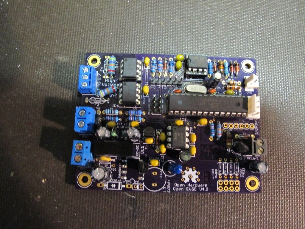
Here is a Version 4.20 board with a 78L05 regulator.

 
djjazzy said:
It's just a plain 6x6 ABS electrical box enclosure, $8 at Lowes.
But with the custom designed Graphics it changes the entire look
of the plain old grey plastic box.

http://www.lowes.com/pd_10029-1716-L5133709_0__?productId=3276255&Ntt=electrical+box+abs&pl=1&currentURL=%3FNtt%3Delectrical%2Bbox%2Babs&facetInfo=#specifications-tab" onclick="window.open(this.href);return false;

Does look very nice. Is the 6 x 6 box plenty big enough to easily assemble everything? Would it be easier in a bigger box - there's really no space problem in the garage.

Also, is the graphics something that you can or would like to pass along?

Thanks.
 
GlennD said:
It was pretty easy to sub the 78l05 for the switching regulator. On other boards I did use the Max5033. Like you I have never used a switching supply. It worked out fine except for the added cost.
Here is a Version 4.20 board with a 78L05 regulator.
Would you be willing to document your 78L05 mod?

Thanks,
Greg C. (Barbouri)
 
Graycenphil said:
djjazzy said:
It's just a plain 6x6 ABS electrical box enclosure, $8 at Lowes.
But with the custom designed Graphics it changes the entire look
of the plain old grey plastic box.

http://www.lowes.com/pd_10029-1716-L5133709_0__?productId=3276255&Ntt=electrical+box+abs&pl=1&currentURL=%3FNtt%3Delectrical%2Bbox%2Babs&facetInfo=#specifications-tab" onclick="window.open(this.href);return false;

Does look very nice. Is the 6 x 6 box plenty big enough to easily assemble everything? Would it be easier in a bigger box - there's really no space problem in the garage.

Also, is the graphics something that you can or would like to pass along?

Thanks.

That 6x6 box is plenty big enough, sure it could be easier to do the install with a larger box, but I didn't think
that was necessary. As for the custom graphics, as long as you won't be making any money or claim it's your design
I'd be nice to have another version of the Leaf Open EVSE out there. Drop me a PM.
 
Barbouri said:
GlennD said:
It was pretty easy to sub the 78l05 for the switching regulator. On other boards I did use the Max5033. Like you I have never used a switching supply. It worked out fine except for the added cost.
Here is a Version 4.20 board with a 78L05 regulator.
Would you be willing to document your 78L05 mod?

Thanks,
Greg C. (Barbouri)

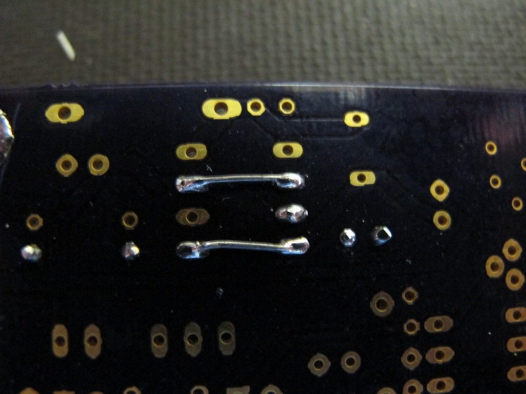
78L05 regulator in a Ver 4.2 board

I installed c16 and c17 for added filtering.

Install a .1 in r22 and c15 (regulator Bypass caps).

Install the regulator in pins 5, 6, 7 with the flat toward the pilot connector.


Bend the input and output pins accress the chip. This connects 4 to 5 and 2 to 7.

That's it. This is a simple mod
 
Thank you Djjazzy. I definitely won't be selling it, and noody who knows me would believe it's my design. You could even add your name or logo to it if you like.

I'll send a PM.
 
I have been hard at work on several OpenEVSE related projects.

I pick up the first batch or Custom OpenEVSE Enclosures from the machinist tomorrow, then they are off to get powder coated and silk screened. It took forever to find a machinist that was willing to do the work. I found a guy with a homebuilt Open Source CNC that agreed to do the work at a reasonable cost... Here is a link to the Blog post... http://openevse-store.myshopify.com/blogs/news/9642495-development-openevse-custom-enclosure

I will have combos that include the enclosure and am working to get high quality J1772 plugs as well.

I also have a couple new boards that will be available in the next month or two. The first is basically an OpenEVSE Plus with integrated 30A relays and current measurement added. It retains all the current features and is smaller than a credit card in both length and width. This board is comparable to the Premium Juice Box but the target price is WAY less....

IMG_20140208_145155.jpg


IMG_20140208_145237.jpg


IMG_20140208_145215.jpg


The second new board under development is targeted for builders of L2 only devices to include International Builders. It will read IEC Proximity pilot and set current based on the cable used and have triggers for cable lock. It will also support a 240v relay coil.
 
Chris' new, DIY 30 amp OpenEVSE board with relays, is a perfect fit in the 2011-12 LEAF EVSE. Now it will do 20 amps and will charge the RAV4EV. Less than $150 and three hours labor. Thanks GlennD for helping with the convertion.

1794902_10152181374363704_1430084836_o.jpg


1898954_10152181579258704_685552389_n.jpg


1781668_10152181577503704_2135426391_n.jpg


1082062_10152181579623704_1588294513_n.jpg
 
Pchilds, nice work.. One note of caution, you don't really want to be drawing nearly 20Amps on a 20A circuit breaker. The general rule is %80 max draw, so on a 20A breaker, you should limit the EVSE to 16A. If you want to charge at 20A, you'll need a larger breaker (like a 25A breaker) and use a 30A outlet, such as an L6-30, or a dryer outlet. Once you go to the 30A circuit, you'd technically need to go to 10AWG wiring as well.
 
mitch672 said:
Pchilds, nice work.. One note of caution, you don't really want to be drawing nearly 20Amps on a 20A circuit breaker. The general rule is %80 max draw, so on a 20A breaker, you should limit the EVSE to 16A. If you want to charge at 20A, you'll need a larger breaker (like a 25A breaker) and use a 30A outlet, such as an L6-30, or a dryer outlet. Once you go to the 30A circuit, you'd technically need to go to 10AWG wiring as well.

I didn't have an adapter for a 14-50, so I tested on a 20 amp circuit. The 80% rule is for loads pulling that current for 3 hours or more, I always turn it off at 2:59 hours. ;)
 
pchilds said:
Chris' new, DIY 30 amp OpenEVSE board with relays, is a perfect fit in the 2011-12 LEAF EVSE. Now it will do 20 amps and will charge the RAV4EV. Less than $150 and three hours labor. Thanks GlennD for helping with the convertion.
Nice - any special tricks to fitting it in there? Are you able to easily adjust the pilot signal?
 
Back
Top