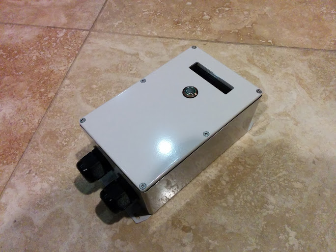
OpenEVSE - Open Source Charging Station

My Nissan Leaf Forum

Help Support My Nissan Leaf Forum:

This site may earn a commission from merchant affiliate links, including eBay, Amazon, and others.
drees said:
Nice - any special tricks to fitting it in there? Are you able to easily adjust the pilot signal?

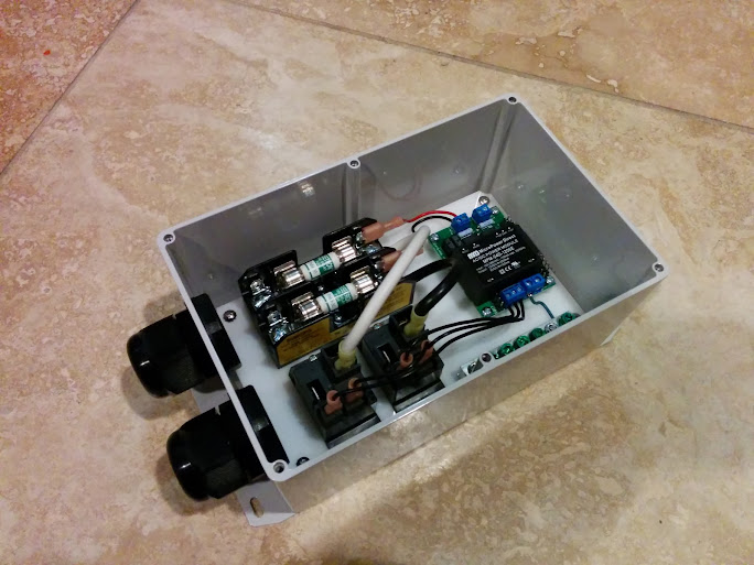
The board is mounted with industrial strength Velcro and low profile lugs for the relays. No easy way to adjust the pilot yet.
 
Hello! I have a 30A combo kit that shipped this morning and am a new leaf owner (my brand new leaf's heater was busted - so it's been at the dealer for 5 days now)..

I have a stupid question:

I want to provide maximum amps for the 6.6kw charger on my 2014 leaf. I will tell the electrician to install a 40A breaker @ 240V. Assuming a 90% efficient charger, I will get a current draw of 30.5A ( = 6600W / 240V / 90% ). The relay that comes with this combo is rated to 30A, so do I need to upgrade my relay & fuse to have a better margin? I suppose I can limit the current to 25A or so, but what is the most I can set this to without upgrading my kit? Can some leaf owners with the openevse comment?

Also, would I use a #8 wire for supplying the power to the openevse?
 
I am hardly the expert here; I'm waiting for the delivery of my 30A kit too. But I am assuming the charger is 6.6kw input, so it is only drawing 27.5 amps (6600/240).

And #8 wire is fine.

If anybody knows otherwise, please correct me.
 
I just "upgraded" my LEAF to 6.6kW charging (by shedding my 2011 and buying a 2013) and just recently upgraded my infrastructure.

I replaced my 20A breakers with 40A, swapped the #14 or #16 with #8 (although #10 is ok), changed the amperage on the OpenEVSE to 30A, and replaced the 6-20L receptacle and 6-20 OpenEVSE plug to 6-30 just to be thorough.

Remember that the LEAF on-board charger maxes at 6.0kW, so the relay(s) will hold.

I'm sure this was just my OpenEVSE, but I noticed after about 10-15 minutes the anderson powerpole connections on the output power to J1772 were extremely hot to touch. I powered it off, snapped off the andersons, and re-crimped new 45A powerpoles. Warm after 30 minutes, but definitely not hot. Probably a bad crimp that didn't care when I was running 16A.
 
Thanks for the replies.

I think my mistake is that I derated the 6.6kw at in the input side. The max this charger can use at the input power is 6.6kw, which translates to 27.5A @ 240V. So no updates. I did say it was a stupid question.

Per z0ner, the charger maxes at 6KW, so the max is 25A, so even better. Are you guys setting the max current in the microcontroller to 27.5A or 25A for the leaf? I am leaning towards 25A.
 
I leave mine at 30A, but like you said, it won't get higher than 25A with the Leaf's OBC no matter what.

@Graycenphil, it's more Nissan marketing. After we determined the OBC only receives a max of 6, Nissan then claimed it draws 6.6kW from the wall, so they can still advertise the higher value.
 
I would even question that - 600 watts lost between the outlet and the charger? Where is it all going, to heat up the J1772 handle?
 
z0ner said:
I replaced my 20A breakers with 40A, swapped the #14 or #16 with #8 (although #10 is ok)
Other than in a couple exceptional cases like motor circuits, #10 copper must be protected by a 30A breaker or smaller. So you did indeed need the #8 copper for your 40A breaker.

Cheers, Wayne
 
I know that Anderson powerpoles are the current ham standard. They have very good wiping action and for temporary use they are great.

Years ago E. F. Johnson used them for power and they were a constant problem. Many service calls involved poor power problems. The fix was to unplug and replug the connector. The very good wiping would fix the problem for a while.

It may be just me but I hate the connectors and I refuse to use them.
 
GlennD said:
It may be just me but I hate the connectors and I refuse to use them.

It's not just you. I think Ingineer can be quoted somewhere around here as well that he wouldn't ever use them in an EVSE.
 
I just realized that it is possible to power the board from the ISP connector. 3 lead regulators hate an output without an input. There is a space for a protection diode across the regulator. Put a 1N4148 in the R21 with the band (cathode) toward the pilot connector.

GlennD said:
Barbouri said:
GlennD said:
It was pretty easy to sub the 78l05 for the switching regulator. On other boards I did use the Max5033. Like you I have never used a switching supply. It worked out fine except for the added cost.
Here is a Version 4.20 board with a 78L05 regulator.
Would you be willing to document your 78L05 mod?

Thanks,
Greg C. (Barbouri)

78L05 regulator in a Ver 4.2 board

I installed c16 and c17 for added filtering.

Install a .1 in r22 and c15 (regulator Bypass caps).

Install the regulator in pins 5, 6, 7 with the flat toward the pilot connector.


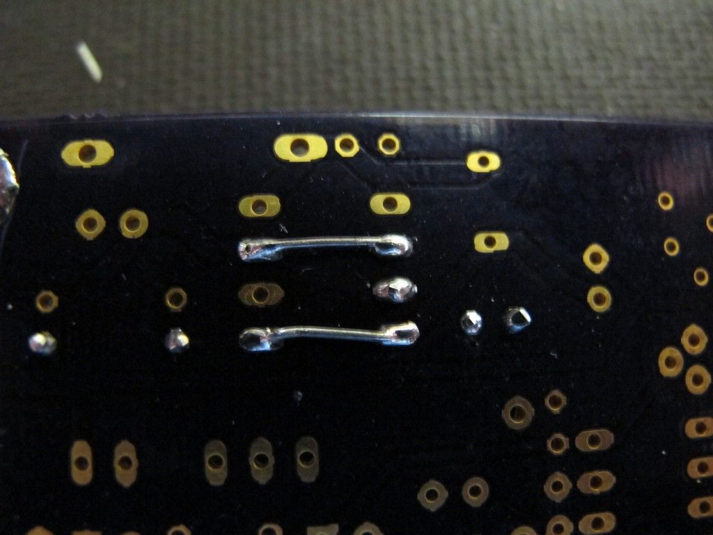
Bend the input and output pins accress the chip. This connects 4 to 5 and 2 to 7.

That's it. This is a simple mod
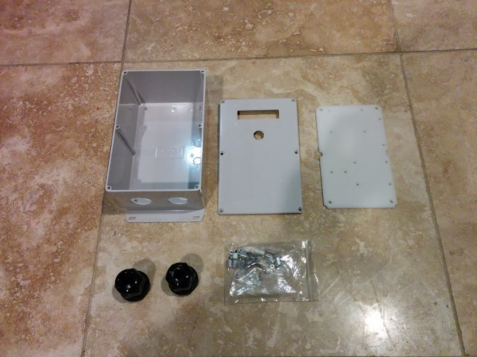
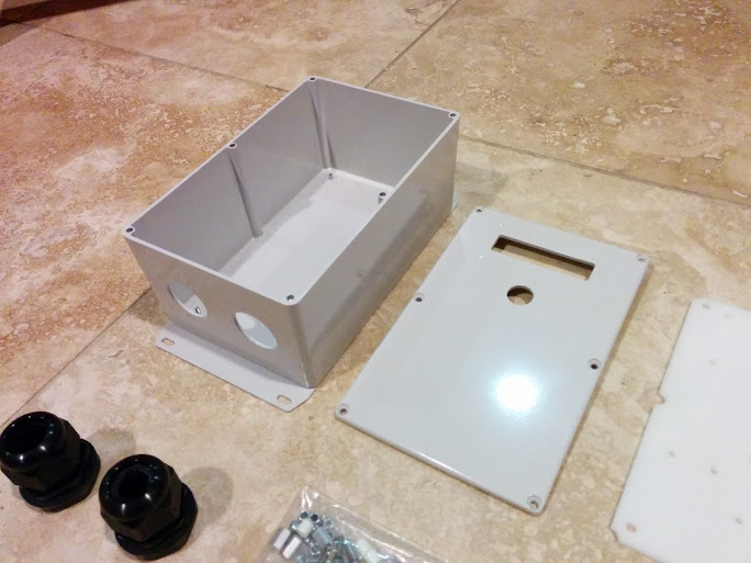
 
I picked up the Enclosures from Powder Coating today... They look Awesome...

All that is left is silk screen and kitting. I made the screens today and will try them out tomorrow.

Here are some pictures of the enclosure without the silk screen and the seal kit.

IMG_20140217_200014.jpg


IMG_20140217_200032.jpg


IMG_20140217_200123.jpg


IMG_20140217_200457.jpg


IMG_20140217_200508.jpg


IMG_20140217_200605.jpg
 
Graycenphil said:
Looks great - maybe I shoulda waited to order my kit...

You'll probably be able to buy the new enclosure, but it's not going to be inexpensive, judging from the work that has gone into it. Engineering your own enclosure is a good excersize too :)
 
mitch672 said:
Graycenphil said:
Looks great - maybe I shoulda waited to order my kit...

You'll probably be able to buy the new enclosure, but it's not going to be inexpensive, judging from the work that has gone into it. Engineering your own enclosure is a good excersize too :)

Mitch is correct. Those who bought the standard OpenEVSE Plus/ Combo can buy the enclosure and install the parts without modification. Send me an E-mail or PM and I will give you a code for free shiping.

The enclosure will cost more than a generic box, but you will save a TON of time and have a really nice looking charging station. The cost will be less than the previously avaliable enclosure from Diversified Stage ($97 - outdoor). Builders will have no fabrication at all and the option for no soldering too, just simple assembly and a few crimps.
 
I've got all the big parts, and am starting to put them together. I need to get a few connectors tomorrow - some big spade connectors f or the 8 ga. wire, and a tiny one for the Ground Fault Coil. I'm hoping Radio Shack sells a connector for that?

As I am studying the wiring connections, I have a silly question. It seems that all the electronics basically serve to turn on the relays. If I just connected my J1772 cable to 240 volts and plugged it into the car, would it charge? If so, what is all the other electronics doing?
 
Graycenphil said:
I've got all the big parts, and am starting to put them together. I need to get a few connectors tomorrow - some big spade connectors f or the 8 ga. wire, and a tiny one for the Ground Fault Coil. I'm hoping Radio Shack sells a connector for that?

As I am studying the wiring connections, I have a silly question. It seems that all the electronics basically serve to turn on the relays. If I just connected my J1772 cable to 240 volts and plugged it into the car, would it charge? If so, what is all the other electronics doing?

Yep a charging station is just a switch but there is more going on behind the scenes. The pilot signal communicates State informarion, current capacity of the circuit, and validates the diode in the EV. It also has Ground Fault Inturupt built in. Plugging a J1772 directly in would not work and light up your dash like a christmas tree with errors.

For the gfci coil I normaly solder and shrink wrap to the pins. If you want a connector a servo extension from you local RC hobby store will work great.
 
Finished, it works, and I am proud. Thanks to all.

I used a big box - 8x8. The picture may make it easier for someone building their first one to see what's going on. If anyone sees any mistakes or shoddy wiring, pease don't be bashful.

1db5877407287533c48b89a481ead5ad.jpg


8b2d1af6c58fedaa3ff2928cbabf0c47.jpg
 
Graycenphil said:
If anyone sees any mistakes or shoddy wiring, pease don't be bashful.
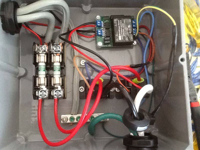
Looks great! I really like the new fuse blocks.

A little extra slack in the J1772 ground and having the pilot tight is good so if it got pulled off the wall the theory is the pilot should break first and the ground last but that's minor AFAIC.

It would be preferable to have the OpenEVSE power leads connected to the protected side of the fuse block, again minor I think.

I wonder what the preferred method of attaching the larger gauge stranded wire to the fuse block. I see three options. Twisted and under one side like you did, split in half and under both sides of the clamp, or a crimp connector.
 
Back
Top