Arduino AT90CAN128 Project

My Nissan Leaf Forum

Help Support My Nissan Leaf Forum:

This site may earn a commission from merchant affiliate links, including eBay, Amazon, and others.
Thanks.

I do need to set up a 0.1 second interrupt routine, and use it to sample/debounce/read the two (Red and Black) push-buttons.

Guidance, or even working code, would be helpful.
 
garygid said:
Thanks.

I do need to set up a 0.1 second interrupt routine, and use it to sample/debounce/read the two (Red and Black) push-buttons.

Guidance, or even working code, would be helpful.
Arduino comes with button reading example.. If you launch the IDE, File->Examples->Digital->Debounce is a debounced button press example. While interrupts are the best way to do buttons, doing it via polling in your main loop is easier, and won't cost much in terms of performance.

I'm pretty sure we could get your code ported over to Arduino very easily. Your C routines would compile fine, all you would need is the CAN stuff, which I can give you. Arduino is just a Java-based IDE which runs on top of WinAVR/avrdude/etc, so the code is all compatible.
 
// Clock prescaler Reset
CLKPR = 0x80;
CLKPR = 0x00;

will override CLKDIV8 and run the clock at full speed. However, it would be best to run those two lines w/ interrupts disabled. In Arduino, you would surround the two lines w/ cli()/sei().

cli();
CLKPR = 0x80;
CLKPR = 0x00;
sei();

Even w/ interrupts turned off, it isn't always reliable unless you do it in assembly language.
 
Thanks.
Good point for when I start to use any interrupts.

I assume cli() is disable interrupts, not clear interrupts?
And, sei() is enable interrupts?

Probably no interrupts are enabled at program start?

I tried to use these anyway in F1.07, and got no complaints.
 
Yes, cli() disables interrupts, and sei() enables them. Actually, they're usually enabled by default.

A clarification on the need for them when setting them on the clock prescaler:

CLKPR=0x80

sets the CLKPCE bit (0x80) so that the prescaler can be changed. The next command,

CLKPR=0x00

clears all the bits. However, it works only if you set CLKPR within 4 cycles of when CLKPCE was set. That's why it might not work w/ certain compilers or compilation settings... the code has to be optimized.
 
Finally found some time to start working on this again.
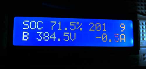
Here's my first live test:

6125106512_fe037baff9.jpg


The top line is SOC %, raw SOC, fuel bars
The bottom line is battery pack voltage and amps.

The amps fluctuate a lot, which is why the number looks dark in the photo.
It actually looks better in person than in the photo. The numbers stand out
better, and the background looks more evenly lit to the naked eye.
I'm using a cheapo HD44780-based LCD that I purchased on eBay a while back.

Currently, it's powered via the USB connector in the console. I need put it into a case.
I'm using CAT-5 cable to connect the LCD. It's too bad, my LCD needs all 8 lines, so there isn't
a wire left for a switch.

Thanks to Gary & Greg for the message ID's and formulas for decoding the data!
 
Great Progress, and nice picture.

Now we need to "decode" more CAN-DATA, and maybe
turbo2ltr had found some more stuff that will be helpful.

RPM (and possibly the calculated MPH, but maybe not)

Tire Pressures

Cell voltages
 
Chris,
Well, we would be pleased to have you playing with us.

However, you have already helped, and been an inspiration
to get something actually working and available.

Let me know what you need.
Try getting CAN-Do, a Recipe file, and a Log file, and get familiar
with using it. Version 1.5.1 should "apprear" in about an hour or two.

Cheers, my friend, Gary
 
Somewhat related thread:
http://www.mynissanleaf.com/viewtopic.php?f=44&t=5113" onclick="window.open(this.href);return false;
 
I admit, within the past week or two I've started considering making my own SoC-meter variant using Arduino, simply because I'd like to have the device be Bluetooth-enabled. That way, instead of a little screen you can read on the box, you'd have a smaller box you could put in the glove compartment, which would talk to an iPhone (or Android) app that gives you SoC in a nice graphical display. That way I could have the handset app even do calculations to show estimated remaining range, as per the SoC/range chart.

Using some of the existing Arduino BT solutions would be a lot less hassle if I was building the solution just for myself. (Though would be a lot more expensive to turn into anything anyone else could use.) But I'd been thinking of just getting a CAN-BUS shield to slap on top of one of my existing Arduino boards...
 
Yes, I thought about using a shield at first, but ruled it out due to cost. The AT90CAN128 board I bought is about the price of an Arduino, and it only needs one cheap IC added to it to work with CAN. Yet, it can still work w/ Arduino tools and libraries. You read my mind. I'm going to add a BT board to it next, so I can display the output wirelessly. The AT90CAN128 has dual USART's inside, so you can support both BT and serial simultaneously.
 
Great minds think alike, or something!

In my case, the reason I was considering the CAN-BUS shield is that I have a currently-unused Arduino sitting in my project box; that seemed cheaper than buying another board. But it sounds like the AT90CAN128 might still be the better way to go. :)
 
For the electronics geeks, I've posted the schematic and code for my SOC meter: http://blog.lincomatic.com/?p=459

Unfortunately, I got too busy to take it beyond the breadboard, but the schematic is for the entire circuit, instead of using the Olimex AT90CAN128 header board, so an enterprising soul can do the layout and make a compact PCB if they wish.
 
chris1howell said:
Nice work lincomatic.

I think I may give it a short. Ill send you a board if I do.

:D that would be very cool. I thought I was going to do the layout on the plane over the holiday break, but kept forgetting to charge my laptop battery.
Maybe Gary could use my circuit for his SOC meter ... I think it can fit into a PCB that's small enough to backpack onto the LCD.
 
I think this is a great idea and after seeing ingeers prototype soc mounted on mirror,i thought what about directly behind the mirror velcroed to the backwall of the flip open sunglass case...easy to snake the cable down from the headrest down windshield pillar (cover removal discussed in tweeter/speaker upgrade thread)That way the SOC is out of sight until you want to actually view data...put me down for a board..kpc
 
Make sure the phone can handle being connected to both your SOC meter AND the car for phone/audio at the same time. I'm far from convinced that can work smoothly.
 
Back
Top