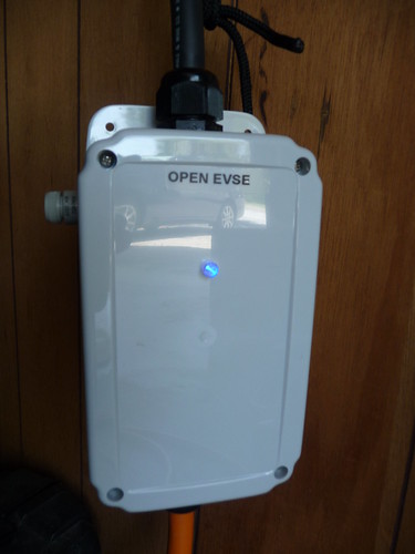
OpenEVSE - Open Source Charging Station

My Nissan Leaf Forum

Help Support My Nissan Leaf Forum:

This site may earn a commission from merchant affiliate links, including eBay, Amazon, and others.
I ordered a display and so I upgraded my portable test unit to get ready for it. Since I am not using your advanced power supply it failed and shut down.

I deleted the lines #define ADVPWR // etc and it compiled fine and it seems to work. Is this the right way to disable the check?
 
Is the proximity detection wire needed with Open EVSE?

I know there was some talk on other EVSE threads like this one:
http://www.mynissanleaf.com/viewtopic.php?f=26&t=6664&p=147133&hilit=150+ohm#p147133" onclick="window.open(this.href);return false;
 
jjlink said:
Is the proximity detection wire needed with Open EVSE?

I know there was some talk on other EVSE threads like this one:
http://www.mynissanleaf.com/viewtopic.php?f=26&t=6664&p=147133&hilit=150+ohm#p147133" onclick="window.open(this.href);return false;

I can answer this one: nope, it has no real function in most EVSE's, it's wired through a resistor and the J-1772 trigger switch to ground, so the on board charger can cut power before the connector is removed, it's all handled by the charger, not the EVSE. Some people have been known to use the wire to supply 12V to an LED mounted in the J-1772 connector, for a "flashlight" of sorts, but you need to changeout the switch in the J-1772 handle to do that, and find a place to mount the LED.
 
mitch672, Thanks for the clarification. I assumed it was not needed since it was not on the diagram, I was just making sure. Thanks

mitch672 said:
jjlink said:
Is the proximity detection wire needed with Open EVSE?

I know there was some talk on other EVSE threads like this one:
http://www.mynissanleaf.com/viewtopic.php?f=26&t=6664&p=147133&hilit=150+ohm#p147133" onclick="window.open(this.href);return false;

I can answer this one: nope, it has no real function in most EVSE's, it's wired through a resistor and the J-1772 trigger switch to ground, so the on board charger can cut power before the connector is removed, it's all handled by the charger, not the EVSE. Some people have been known to use the wire to supply 12V to an LED mounted in the J-1772 connector, for a "flashlight" of sorts, but you need to changeout the switch in the J-1772 handle to do that, and find a place to mount the LED.
 
Since the ITT cable has a blue wire bringing the prox switch out I use it to trigger a relay. I have a small circuit that has a relay that opens the pilot when the button is pushed.
 
GlennD said:
Since the ITT cable has a blue wire bringing the prox switch out I use it to trigger a relay. I have a small circuit that has a relay that opens the pilot when the button is pushed.
Wouldn't that just be likely to interfere with the intended use of the proximity switch?
 
My leaf does not seem to use the prox signal. Nothing happens when it is pressed.
The relay circuit is using a darlyron Sp? MPS-A13 transistor so it is high impeadence and it has no loading of the existing levels.
 
GlennD said:
My leaf does not seem to use the prox signal. Nothing happens when it is pressed.
The relay circuit is using a darlyron Sp? MPS-A13 transistor so it is high impeadence and it has no loading of the existing levels.
You wouldn't know unless you were monitoring current on the AC lines. There's no obvious sign that the car's charger has cut the draw.
 
davewill said:
GlennD said:
My leaf does not seem to use the prox signal. Nothing happens when it is pressed.
The relay circuit is using a darlyron Sp? MPS-A13 transistor so it is high impeadence and it has no loading of the existing levels.
You wouldn't know unless you were monitoring current on the AC lines. There's no obvious sign that the car's charger has cut the draw.

FYI, on my PiP, when the trigger is pressed, the green "charging" light next to the J-1772 inlet goes off immediately.

The display in the car also shows "charging interrupted by user" or something similar.
 
The LEAF does respond to the list proximity but it is not obvious from the outside. It has been verified by several MNL members that current drops to almost zero when the switch is pressed. Dropping the pilot from the EVSE will only provide a benefit if the EV does not comply with J1772.

J1772 requires the EV to terminate charge within 100ms of proximity activation. The EV is also required to terminate charge with loss of the pilot but it has 3 seconds to respond. So if the EV does not comply with proximity and fails to terminate charge, killing the pilot will do the same thing but you may have to wait to disconnect if the EV does not respond instantly.
 
Interesting, I put a clamp on meter on the ac line and the proximity switch DOES shut down the charger.
The pump continues to run and no indicators change at all. As far as the world is concerned it is still charging.
 
GlennD said:
Interesting, I put a clamp on meter on the ac line and the proximity switch DOES shut down the charger.
The pump continues to run and no indicators change at all. As far as the world is concerned it is still charging.
It makes sense if you think about it. If you've pushed the button by mistake, and just release it, no sense shutting things down and cycling the EVSEs contactor, and if you are unplugging, the charge will end when you do.
 
Just received my latest version of thru-hole Open EVSE boards today.
Boards were made using Laen's DorkbotPDX PCB service.

I added voltage sense inputs similar to the Advanced Power Supply board, along with a separate power sense board.
There is also the capability of controlling a second relay, and a header for connecting to an Adafruit color LCD shield.
Also added is an onboard +/- 12 volt DC to DC converter that is powered from the 12 input.

7155084512_764c9e0544.jpg


Voltage sense board
7155084306_a8973a3f7e.jpg


I will post an update once I have a board populated with components and tested.

Greg C.
 
I received a couple of Backpack LCD boards from Adafruit today. I noticed the code was already setup for the backpack board so I enabled it. With Aurdino 1.0 it complied with errors. I tried the hello world example in LiquidTWI and it also error-ed. From the Adafruit site they said 1.0 broke the program samples so I downloaded .0023. This compiled just fine.

I now have a working white on blue display to mount in my portable EVSE. It displays all of the messages that my RGB shield does and it is much smaller.

I plan to rebuild my fixed charger to use the color RGB shield now that the portable EVSE can stand in. I just have cut an opening and mount the display. I built the fixed one in a hurry and I did not even paint the case. I have a smaller relay that will allow room for the display.

The display adds no functionality to the EVSE but its really cool looking.

While bumbling through the code to me it looks like the watchdog timer is commented out. Am I missing something?
 
Update on thru-hole Open EVSE boards

Finished populating and testing the updated circuit board.
Tested at L2 16 amps using v 0.5.0 firmware by Chris Howell.
Passes "Power On", "Stuck relay", "Earth Ground", and "L1/L2 detection" tests.

Not Connected ready
7199849568_d44245f5a7.jpg


Waiting for EV
7199848932_1ba4b561b6.jpg


Charging at 16 amps.
7199850146_d1909fbb89.jpg
 
Barbouri,

I'm sure many with existing OpenEVSE's might be interested in your "voltage sense" board, for adding in L1/L2 detection, stuck relay testing, and verifying the ground as well... Nice job on the boards. At this point it seems like the voltage sense and the power supply could all be added to 1 larger PCB, and simplify the design, probably even the AdaFruit RGB LCD display circuitry could be added as well, making a complete EVSE that assembles easily, apply 120/240 input power & ground, the test AC power at the switched relay as inputs, and then 1 or 2 12V relays and the CT coil, done. Just needs a nicely designed case to contain it...
 
Back
Top