Mini-QC Rapid-Charger (RC) Project for LEAF QC Port

My Nissan Leaf Forum

Help Support My Nissan Leaf Forum:

This site may earn a commission from merchant affiliate links, including eBay, Amazon, and others.
I guess I'll start this part going since yesterday at the meet I said I would.. and I told Robert last night I would start posting info/specs, etc.. (and I just got your email ;) )... I just got home right now..

INFO TIP #1 about these units (they are all made from either Delta electronics, they make the FUJI CHAdeMO systems), FSP or HiPro.. That's probably it.

http://www.delta.com.tw/product/rd/evcs/evcs_product.asp

TIP#2 These are LIGHT YEARS ahead of standard PC powersupplies.. even the "fancy" big names like Corsair, ANTEC and CoolerMaster.. they are still junk compared to these "Enterprise Class" units.

TIP#3 They will run ALL DAY LONG in a 135*f server closet who's AC unit has failed and keep on ticking.. no issues...

FACT#4 They can be regulated (Audrino,etc)... They CAN BE ISOLATED.. and they CAN BE paralleled for ANY power output you want.. I HAVE DONE IT, many others have done it.. I was one of the first contributors on the RCGroups thread that started to help people back in 09 work on this project..

FACT#5 :lol: I have not "attempted" to push beyond 160vdc with a string of them because there was no need to. Now that I have the Leaf... well... you see my sig below :eek:

Here's some links if people want to get started.. THERE ARE A TON OF DIFFERENT SUPPLIES OUT THERE.. USE THIS AS A STARTING POINT TO FIND YOURS

http://www.rcgroups.com/forums/showthread.php?t=1292514

The above link will have almost ANY POWERSUPPLY AVAILABLE!!.. pinouts, schematics, specs, etc..

Now for me..... :twisted: :D

I've been "kinda working" with a 3000w unit for awhile (well... not too long)... It's a HP 46-52v 3kw BEAST!! Here are some great links and places I've been getting info from..

http://www.rcgroups.com/forums/showthread.php?t=1823759
http://endless-sphere.com/forums/viewtopic.php?f=7&t=32829
My fav place... CNC zone has a great thing on this PS..
http://www.cnczone.com/forums/gener.../112704-hp_server_power_supply_51_4v_57a.html

I've been testing this unit to charge my solar battery bank.. it puts out a TONS of current!! And they can be had at a decent price.. For me...

8*49vdc=392vdc to the pack at 57amps !! Ohhhh yeah! :twisted:

And of course.. the thread that started it all...
http://www.rcgroups.com/forums/showthread.php?t=1005309

Any way that I can help guys... let me know!
 
Great initial report on these, Jim. So looks like 7lbs apiece. 2 60mm high speed fansfor 300 watts in heat loss sounds about right. Doesn't matter how many of them we use at the same time as long as we have fresh ambient air going into each of them.

Our boost PFC stage is 93-95% efficient when producing 420-440v required for a leaf (97% at the standard pfc output of 370 in our chargers targeted at ev conversion guys - the more boost you need to do the less efficient it becomes). Buck is 98-99% efficient at 12kw 400v output.

I think we can get 92-93% efficient isolated buck (half bridge) if we get the magnetics sorted out. The reason these delta supplies are only 80% is low output voltage. It becomes progressively trickier to increase efficiency as you lower the voltage. Diode drops alone will eat 3-5%. Fet voltage drops - another another 3-5%. So you are out 10% before considering switching losses, magnetics losses, caps heating etc. By doing isolation at high voltage one would save at least that initial 10%.

I don't think we should care much about the schematics of these. We will use them as simple regulated 48v supplies. Black boxes. All charging control will be done outside of these. This way we get to reuse the work that this group already done on control side of the 12kw supply you are using. Also, when we get our isolated buck done, it will be trivial to adapt.

Gary, since you asked to post here instead of pm: I would like to replicate your control stage on our side. We have a bunch of avr cans here but also (as you probably heard from Robert) we just ported all our control stage to a new board with arduino due, dual can, wi-fi, rtc, sd, large eeprom, etc. I think that would be an ideal platform for continued development of the control stage for this qc unit. We have the boards and they are being tested now. But first i'd like to replicate your current setup with avr-can in our lab.

How can we do that?

Thanks
Valery
 
Gary,
I have no Leaf, so naturally I have not signed anything about reverse engineering

I weighed my units (without packaging) and since I do not have a very accurate scale,
I stacked 10 units on it, which were a total 72 lbs, so each is 7.2 pounds (3 1/4 kg)
which is much heavier than I expected. But yeah, these are professional units with
half-million hours MTBF (Mean Time Between Failure) at room temp.

Pinout of the units and the full spec can be found here:
http://www.rcgroups.com/forums/showthread.php?t=1621433" onclick="window.open(this.href);return false;
Click on the FH1500 document to get the datasheet.
To just power up the unit, connect the Kill and the Off/On pin to the 12V Standby Return (ground),
all these 3 are adjacent pins in one horizontal line, the Kill pin is the one shorter pin.

The units do not need to be opened to power them, even marginal voltage control should
be possible via the connector and also feedback about failure is available on the connector.
To open, more than a dozen glued-down screws must be removed, so use a *good* fitting
screwdriver or you will strip them.

As I said before, the case ground is only referenced by the 12V standby output and
the control signals, the 48V output is floating and allows up 1500V to ground.

There is one area that for prototype testing is not so important, but for a product
MUST be addressed and that is response to protection (failure or overload/overtemp)
of a unit. Since the Buck output stage has a negative input resistance, the shutdown
of one unit will cause an even greater load on the other units in addition to presenting
a (possibly large, destructive) negative voltage across the output of the unit that
went down (Unless adding protection diodes across each output).
So, the FAIL signal from each unit must be tied to the input of a circuit to KILL
all other units immediately (The Kill input will stop output without waiting for the
caps to drain, so it avoids that things are blown up with the energy from the caps)
So, in the production version the Kill input must not be hard-wired, so that one
unit overheating, overloading or otherwise not delivering its output will cause the
whole stack to stop output and safely shutdown.
Since the Fail output and Kill input signal are ground-referenced, the circuit can be
shared between all units without galvanic isolation.

To professionally connect these units, the Tyco Multi-Beam XL connector 1450540-1 can be used
or the 1450160-3 (right angle, solder pins)

This week, I will take some pics of the opened supply to point out the output voltage regulator if you are
interested and I will continue to chase the overvoltage protection circuit so that I can get a bit
higher voltage out of these units, probably high enough to deliver the max 450V from 8 units.

I understand the risks of working with high voltage and power and (incomplete) software,
since I have been working in Electronic product design since about 30 years and have
installed batteries in my own EV (312V pack), so that is why I would appreciate to get
the control software at the state that it has today, to see what I can contribute to
the present developments and where it makes sense to choose a certain architecture
to make this fast charger available to more Leaf (or other EV) owners.
I myself am planning to build a circuit to control a number of these supplies
to charge my own EV.
I already ordered a CAN-AVR and received 3 loose (sample) Atmel AT90CAN128 controller chips
plus I received some CAN interfaces (same as on the CAN-AVR, so that I can
build a few independent controllable chargers, once I get some software hacked together.
So, I would very much appreciate a pointer to the current state of the software.
 
Cor said:
Gary,
I already ordered a CAN-AVR and received 3 loose (sample) Atmel AT90CAN128 controller chips
plus I received some CAN interfaces (same as on the CAN-AVR, so that I can
build a few independent controllable chargers, once I get some software hacked together.
So, I would very much appreciate a pointer to the current state of the software.

+1

I also suggest (as I did already in my previous post) that we use Arduino Due for 'production' version. Once you start running extensive CAN comms, add more logic to the system, try to control multiple stages, you will need more power, program memory, and RAM than AVR-CAN can provide. There is now a full-featured fully open source CAN library for Due that works perfectly.

The current board we are testing now is below. After we are done with testing and confirm operation on our chargers (code porting should be minimal as we preserved all pinouts etc), I can send a few to whoever wants them at cost.

Thanks,
Valery.
 

Attachments

  • EMW12K_DueControl-Assembled_renamed_3888.jpg
    EMW12K_DueControl-Assembled_renamed_3888.jpg
    153.6 KB · Views: 93
  • EMW12K_DueControl_renamed_9639.jpg
    EMW12K_DueControl_renamed_9639.jpg
    157.1 KB · Views: 93
Valery,
I can't help you with the CAN interfaces (other than pointing to the Ebay auction where I got them) as I ordered
and already received DIP versions of them - easier to handle while experimenting.
Here is the auction for them: http://www.ebay.com/itm/321085321931" onclick="window.open(this.href);return false;
They arrived so quick since this seller is in the area (Eastbay) instead of in China or Hong Kong.

I have quite some experience in (re-)designing the architecture of software to improve real-time behavior.
You'd be surprised to know what you can do with a small processor if the architecture is chosen carefully
to offload all processing intensive tasks to hardware (such as generating PWM signals for the buck converter)
and the software is mostly doing some general control settings and not much data moving or bit shuffling.
Most work I have done was on 8051 and 8086 processors, a bit on 68k but also I build a complete I/O board
for a digital TV, including a small micro that was seriously lacking in memory space, but still had to handle
several communication buses. Most my programming was C or asm. So, once I have the CAN-AVR, I will
explore the CAN application that does the serial conversion and then see what I need for the ADC and
design the DAC interface to control the supplies, then see if I can integrate the Leaf-specific commands, if
Gary can share some of that, and control the charger in I or U.
 
JasonA,

Here's some links if people want to get started.. THERE ARE A TON OF DIFFERENT SUPPLIES OUT THERE.. USE THIS AS A STARTING POINT TO FIND YOURS

http://www.rcgroups.com/forums/showthread.php?t=1292514" onclick="window.open(this.href);return false;

The above link will have almost ANY POWERSUPPLY AVAILABLE!!.. pinouts, schematics, specs, etc..
This link seems to deal with 12v supplies only, and stacking two, not many.

As was pointed out above, controlling what happens to a 450v stack of 8 or 9
nominal-48v supplies when one faults (perhaps due to over-temperature) is
something that one needs to consider.

----------------------------
There are several parts of the system that one should build and test
before connecting to the car. One possible List (not all steps included):

Depending upon the hardware that you select, we might be able
help or make suggestions with some of these steps.

CAUTION: Use all this equipment entirely at your own risk.

We started with Valery's 12 kW Kit, with Power Factor Correction,
and replaced its buck-stage control as needed for doing QC.

Valery might be able to sell buck-stage kits to those trying to use
stacks of 48v supplies, or the equivalent, for a DC Front End.

1. Build the Power Supply, and Control the voltage and current output,
using a uP. We started with an AVR-CAN, but the 10-bit PWM
was found to have not quite enough resolution for the job really well.
In trying to use the Arduino Due, with its 16-bit PWM circuitry,
we find that the Due Libraries are not ... yet complete.
Apparently Valery has had different experience.

2. Monitor the uP and the PS with some kind of manual Command and
Control center. For testing, use a high resistance to ground from each
High Voltage lead, perhaps 200k ohms, to demonstrate centering the
isolated output around ground, as the car would expect. Measure and
log the +HV to ground voltage, and the +HV to -HV voltage.

3. Create logging of the PS and Control functions, control values,
current, voltages, temperatures, etc.
We create a pseudo-message ".qcc" CAN-Message file so that we
can look at the log with CAN-Do, anticipating adding the logging of
the incoming and outgoing QC CAN Messages.
Real-time monitoring and control, and logging for later analysis
of fast-occuring and critical-timing events is usually very helpful.

4. Include effective safety and shutdown procedures.

5. Testing open-circuit and then using a high-power resistive load, log
demonstrations of the ramping up and down of the output voltage,
and demonstrating ramp-up of current, and current shut-down.

6. Prepare to operate and sense the four QC control lines, and log the values.
One can see the open literature descriptions about how these control lines
are meant to be used. Usually the timing is omitted.

7. Prepare tp receive CAN Messages from the car, and log them.
Typicaly we observe packs of 3 messages, with packs once each 0.1 second.
So, not a high average message rate, but the three can come close together.

8. Prepare to send two CAN Messages to the car, in response to those
received from the car. The data bytes can be inserted later.

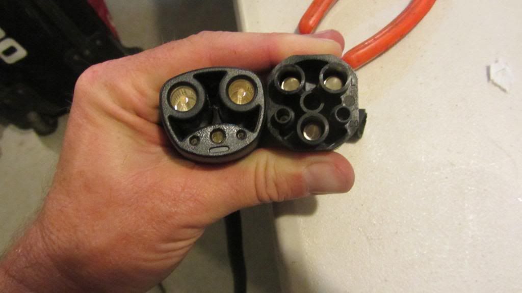
9. Qualify to get, for private, indoor, cautious use only, a Jolomo QC plug,
or qualify to 3D print one yourself. Make or obtain pins for the connector,
two 9mm for Power, seven 1.5mm for control. Get them silver plated, if possible.
I have some pin and plug drawings and assumed plug dimensions, and Joel
has 3D CAD for printing the plastic parts. The latest even has a manual latch.
He has been doing a splendid job of collaboration with data going both ways.

11. Obtain suitable wiring for the mini-QC cable and connect the Plug.
After wiring the Plug, do not yet connect the two HV wires to your Power Supply.
You should run more tests before attempting to apply HV power to the car.

12. Submit CAN-Do logs of your tests and schematics and pictures of your setup
and equipment for us to review. We might define some tests to run and log.
We wish to encourage safety at all steps of the process.

13. Get more info on the QC-CAN messages, going both ways.
If you have used use the on-line QC-Log with CAN-Do, you can
already see most of this info.
But, that log is not perfect, so use the info at your own risk.

14. Through observations of our Logs, of real-world QC sessions and
our own many esperiments, we have gradually developed some ideas
about the meanings of the data in the QC-CAN messages.

Since this is not public iformation, we feel that it is premature for us
to share our guesses and assumptions about the QC messages at this time.
 
This design process would be easier if we had a short female-to-male
QC adapter that would log everything passing through it.
For that, we just need to find suitable female pins.

Similarly, a standardized manual monitor and control module
for the mini-QC charger's control section would also be useful.

Cheers, Gary
 
Cor said:
Valery,
I can't help you with the CAN interfaces (other than pointing to the Ebay auction where I got them) as I ordered
and already received DIP versions of them - easier to handle while experimenting.
Here is the auction for them: http://www.ebay.com/itm/321085321931" onclick="window.open(this.href);return false;
They arrived so quick since this seller is in the area (Eastbay) instead of in China or Hong Kong.

I have quite some experience in (re-)designing the architecture of software to improve real-time behavior.
You'd be surprised to know what you can do with a small processor if the architecture is chosen carefully
to offload all processing intensive tasks to hardware (such as generating PWM signals for the buck converter)
and the software is mostly doing some general control settings and not much data moving or bit shuffling.
Most work I have done was on 8051 and 8086 processors, a bit on 68k but also I build a complete I/O board
for a digital TV, including a small micro that was seriously lacking in memory space, but still had to handle
several communication buses. Most my programming was C or asm. So, once I have the CAN-AVR, I will
explore the CAN application that does the serial conversion and then see what I need for the ADC and
design the DAC interface to control the supplies, then see if I can integrate the Leaf-specific commands, if
Gary can share some of that, and control the charger in I or U.

Hi Cor - tranceivers are in the mail to us from DigiKey so we will be putting them on to complete the picture in the next couple of days. But thanks for offering help.

I would suggest us all to standardize on the same platform even if it means some of us have to learn a bit more. Figuring out how to properly control an unknown supply is, while a lot of fun, is not an easy task and will consume a lot of time, most likely some parts and some supplies, as well. I suggest we first demonstrate isolated operation of the existing control setup that Gary and company have developed. Then we can move to a better hardware platform for control. Due seems good enough to me but if people have other ideas that make more sense, let's do that. Then once we get that working, we will try to make an isolated high-voltage output stage.
 
Valery,
If you do not mind saying, what do you actually have working
with the Arduino Due now, or expect to have soon?

Could people buy a 12 kW buck-only kit from you?

Caution to all:
The Due is a 3.3v only part, and using traditional 5v parts need
special interface considerations.

We had no major problems using the AVR-CAN board, except:
1. We only got one A-to-D to work well, so we added an external
opto-isolated analog mux.
2. The 10-bit PWM needed more resolution to do the output
current regulation better.
 
garygid said:
Valery,
If you do not mind saying, what do you actually have working
with the Arduino Due now, or expect to have soon?

Could people buy a 12 kW buck-only kit from you?

Caution to all:
The Due is a 3.3v only part, and using traditional 5v parts need
special interface considerations.

We had no major problems using the AVR-CAN board, except:
1. We only got one A-to-D to work well, so we added an external
opto-isolated analog mux.
2. The 10-bit PWM needed more resolution to do the output
current regulation better.

Hi Gary - sure.

We have ported our current control stage for the 12kW units to the Due. This includes the remote UART control we have added to our systems in August. This also includes the 'slow' control code for our prototype PFCdirect 25kW units. The code works on a Due but we haven't completed full system testing yet (i.e. charging our cars with a new control stage). I don't expect any surprises, though.

What we have not done is any of the 'fast' control mods that you guys had to do to make the system work for the QC purposes. We also have not yet tested the CAN comms (but have many reports from other people who made CAN-DUE work for their purposes).

Just so people understand what I'm talking about re fast and slow here. Our standard code for the 12kW PFC+buck units (which is a relatively mature product), and prototype 25kW single-stage PFCdirect units has a relatively dumb, slow PWM update logic - with simple duty increment per ~100ms cycle or 1%/second. This is insufficient speed for the QC purposes. Hence part of the rewrite that Gary & team had to do was making the PWM control much faster. Now, we did implement the fast PID control for our prototype DC motor controllers using the same control stage based on Arduino Pro Mini. The fastest stable ramp we got working there is above 1000%/second. Works fine but we did not have the need to match the same speed in our chargers - until now.

To your question on 12kW: people can definitely get one of our buck stages now - it's very close to our standard non-PFC kit, sans a couple of components. Can be had in either a kit or assembled form. Pls PM me if interested.

Thanks,
V
 
garygid said:
This design process would be easier if we had a short female-to-male
QC adapter that would log everything passing through it.
For that, we just need to find suitable female pins.

Similarly, a standardized manual monitor and control module
for the mini-QC charger's control section would also be useful.

Cheers, Gary

Not sure exactly why you still would need this, I thought you had just about all the data mapped out already...
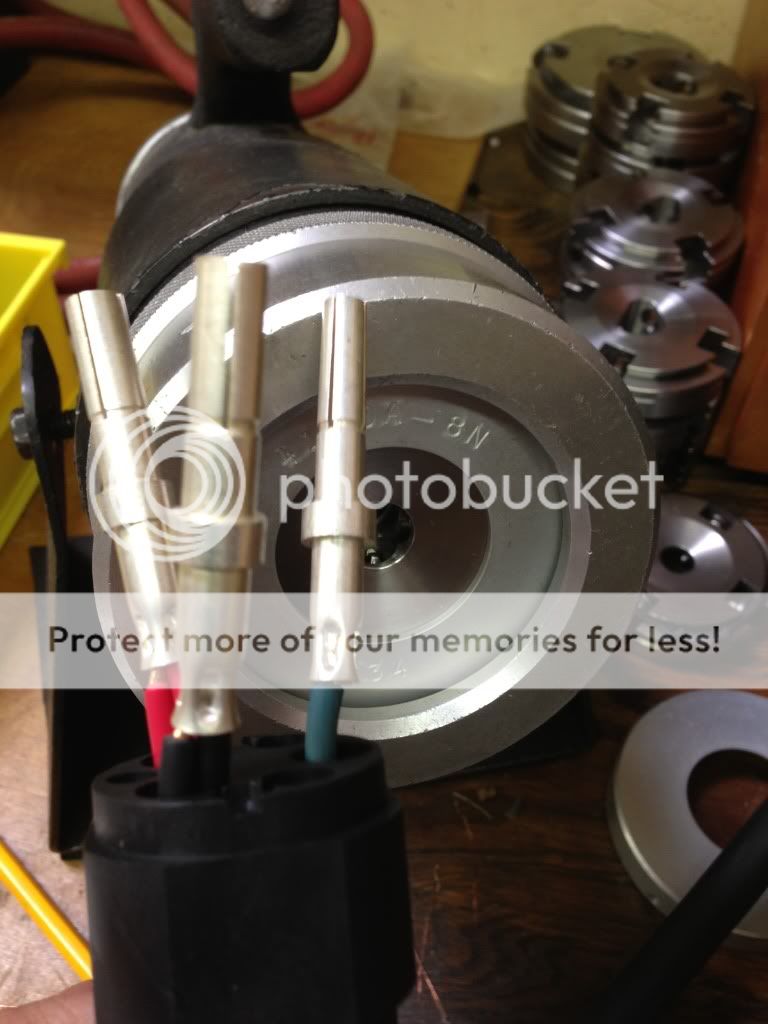
Anyways, I found something rather by accident, I was looking for female pins that could be compatible with J1772, and found this instead.

bear with me, there are lots of part numbers here for reference.

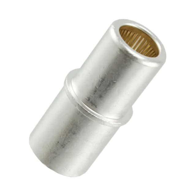
I found this part on digikey, which describes the size as #0, which means essentially nothing other than it is their biggest one.
6648405-1.jpg

The drawing for this does not even indicate the diameter.
http://www.te.com/commerce/Document...8405&DocType=Customer+Drawing&DocLang=English

This system is described in this catalog (see pages, 64, 81, 82)
http://documents.tycoelectronics.co...hENG_CS_1773096_SEC02_CABLE_MOUNTED_0210.pdf

But I have seen the male pins for these before, and I knew that they have the diameter in the drawing, I found the mating part number in the big catalog above (pg 64)
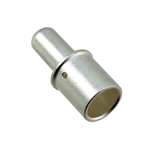
Here is the male pin
1766811-1.jpg


according to it's datasheet,
http://www.te.com/commerce/Document...6811&DocType=Customer+Drawing&DocLang=English
The diameter is 0.357 inches with a tolerance of +/- 0.010. (so this would mean 0.347-0.367 inches or 8.8138-9.3218mm)
This is right on the money for the chademo pin which has a much tighter tolerance. I am talking about putting our chademo pin into the female contact which was designed to hold the 0.357in pin. Did I mention that this contact is also rated for 200A?

male pin digikey pn:
1766811-1-ND

female inlet digikey pn
6648405-1-ND

booya
 
jclemens said:
male pin digikey pn:
1766811-1-ND

female inlet digikey pn
6648405-1-ND

booya


I think #0 means AWG 1/0. According to http://en.wikipedia.org/wiki/American_wire_gauge" onclick="window.open(this.href);return false;, 150A ampacity at 75C temp rise. We could probably go for AWG 4 wire for this (85A at 75C rise - or ~35kW at Leaf's voltage - plenty enough for now I think)

These pins are too short though, no?

Valery.
 
Yes the male pins are too short, that was not the point, the context was the female pins. If we really need them, we could buy a few and drill out the middle to solder a couple in series, this would envelop the entire male pin, though i'm not sure it is necessary because the current rating is 200A
as for the awg, the diameter of the crimp hole is over 11mm, you could fit a 0000 cable in there if you were so inclined.
 
If you put a boost stage behind e.g. the server power supply, which is already isolated, can this be designed to boost e.g. 48 V to 450 V ?
This way, the power supplies can be used in parallel and no issue would arise if one of them fails?
 
klapauzius said:
If you put a boost stage behind e.g. the server power supply, which is already isolated, can this be designed to boost e.g. 48 V to 450 V ?
This way, the power supplies can be used in parallel and no issue would arise if one of them fails?

possible but less desirable. The more you have to boost, the lower the efficiency. 48->450 booster will have 85% efficiency at best. Also, input currents of 250A are not easy to deal with.

One thing you *could* do is to add a booster for each supply. 1.5kW / 30A is relatively easy to manage with small inductors, etc. You will still have to deal with 85% efficiency.

85% boost efficiency * 80% original supply efficiency = 68% total efficiency. So you would be losing entire 1/3rd of the power that comes in. Not fun (both from cost standpoint and managing the heat).

those ferrite cores for high voltage isolator are on their way to us now but I'm not promising anything ;-)

V
 
jclemens said:

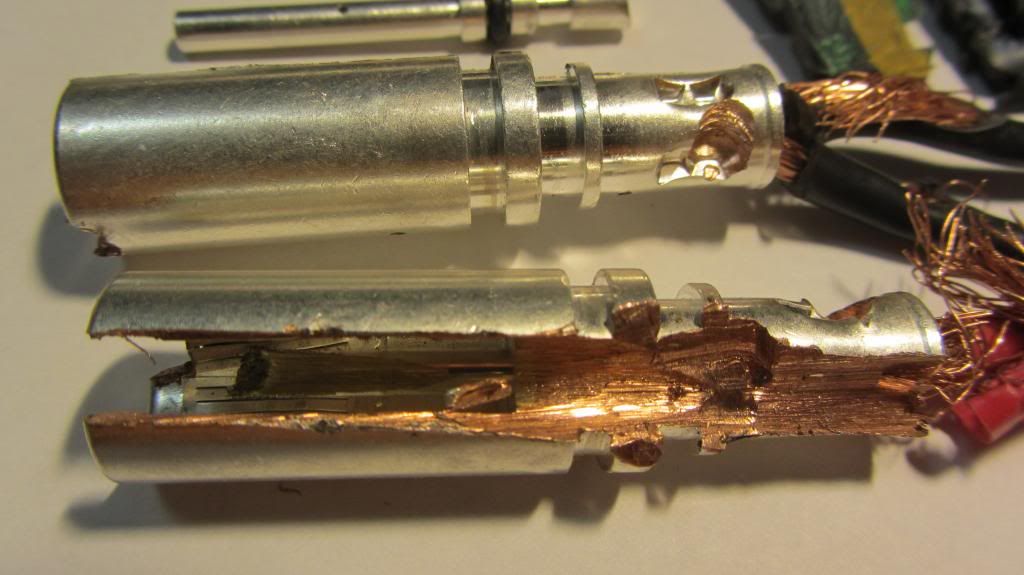
I cut open a Tesla socket (below) to check out the materials used. It shares the "low contact engagement" technology similar to what Amphenol calls "Radsok". I notice that the Digikey pins above use a variation of this, too.

Anyway, one simple question. Do we have specifications for the CHAdeMO pins? Im no asking for guessing, but actual hard data? If so, that may be a contribution that I can provide.


IMG_2130.jpg
 
jclemens said:
gaaah! Tony, you are insane for wasting those contacts!
any idea what the dimensions are??

I have lots of them. Not wasted, it's education.

Those pins are actually coaxial (it's difficult to see the center pin in the photo). Designed for 400 volts at 300 amps (120kW). I'll measure them later.


IMG_1869.jpg


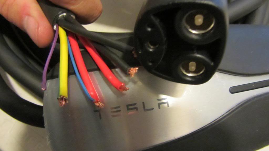
Tesla plug on the left, J1772 on the right:

IMG_1867.jpg


Here are the pins I'm using for my Tesla to J1772 conversions (and my professional crimping tooling):

null-6.jpg
 
If anyone is considering using a bunch of 48V power supplies in series to make a QC, why would you then add another buck (or boost) stage? Why not just control the existing PWM circuit in the bank of power supplies? Probably as simple as adding an optoisolator (you might not even need that depending on the power supply design).

These enterprise-class power supplies are usually very well engineered and have good efficiencies, so it seems silly to add something external, thus adding loss, when you could just control the existing circuit. In addition, you'd be dealing with high voltages and currents in your buck stage, so any failures could be catastrophic. (For you, your LEAF, or your home!)

As Cor mentioned, In series operation a failure of one unit could result in high voltage reverse polarity applied to the outputs. There absolutely must be some investigation done and possibly modification to harden the system. Applying high-current reverse DC to the output would most likely result in the large electrolytic filters exploding and/or venting. Even a momentary reversal at low current could result in destruction of the output sensing and feedback circuits. When you are dealing with this much power you must not cut corners and "rig" it.

-Phil
 
TonyWilliams said:
Anyway, one simple question. Do we have specifications for the CHAdeMO pins? Im no asking for guessing, but actual hard data? If so, that may be a contribution that I can provide.

See page for of this datasheet
http://www.dyden.co.jp/topics/data/pdf/evkyusoku17p.pdf

It gives the diameter and tolerance of the male pins.
The lengths we had to figure out on our own based on simply measuring the pins on publicly accessible stations.

that gave birth to this:
9mm_power_pin_display_large.jpg
 
Back
Top