2020 Leaf Rear Window Defroster Offline

My Nissan Leaf Forum

Help Support My Nissan Leaf Forum:

This site may earn a commission from merchant affiliate links, including eBay, Amazon, and others.

knightmb

Well-known member
Joined
Jan 12, 2015
Messages
2,214
Location
Franklin, TN
I'm certain that my Rear Windows Defroster is not working. The first thing I did was check the (2) 15A fuses for it. I did measure the power usage when I turn on the Rear Window Defroster and it was only about 12 watts of power, which is likely the heated mirrors, but the large traces on the back window appear to be offline (no power). I did notice that I don't hear the usual "relay" click when I turn it on, so I suspect the relay is the issue. I'm not able to "easily" find the relay location to check it online.

Anyone that is more knowledgeable on this subject that knows which relay operates this, the info would be greatly appreciated. I am aware of the fuse box and relay box under the hood in the front, but I don't want to start tinkering with stuff until I know what I am tinkering with exactly. 😵‍💫
 
A quick look at the wiring diagram shows both the side mirrors and rear defrost are on the same relay and same side of the relay, if side mirror has power the rear should also.
Pull the hatch cover off if the side mirrors have power and check for power and good ground in the hatch. There is a "noise condenser" in the hatch that feeds through to the heater grid. so check for input at the condenser as well, it will be a little item that is to the left of the rear wiper motor.
Come to think of it, does the rear wiper work? If not that might indicate a ground issue?
Again from a 2015, but not sure it would be different on a later car.
 
Good questions, the rear wiper and brake light work fine. I would assume the ground connection to the rear hatch door is good then. I'm going to fog up the mirrors to see if they actually will defrost themselves to account for the low power usage. If that passes, then it seems like I'm going to need to inspect the wiring that leads to those heater traces on the rear window.
 
I should be about to examine more today, the weather has been cold and raining for days so I just couldn't do anything with it outside. I did find out via the cold and rain that the traces are working because when I turn it on, it would warm up just enough to clear a small area around the traces, but not the whole window. Odd behavior for sure. Going to do some better testing to figure out what is going on.
 
Very odd. If there's a voltage drop somewhere else that's causing this, like at the connector(s) or relay contact, then those would be getting warm. But you can measure voltage at the hot side and that will tell you a lot. And is the other end a dead short to ground?
 
Right now I'm fogging up the window with an ultra-sonic humidifier to verify what I saw some days ago when it was raining and cold. Currently, just measuring the circuit from the fuse box I only see about a 1 amp draw, which is roughly 12 watts of power. Certainly nowhere near the 200 watts it normally uses. My guess; that is either powering the mirror heaters or the whole thing is being clamped on power, so when I do the mirror heater test it may not even be enough to clear those. 😒
If only I had a good FLIR camera. :LOL:
 
Well it seems only the passenger side heater mirror is working. My driver side mirror is not and I can verify the rear window traces are certainly not working. What I saw days ago was probably just the metal itself conducting a little heat from the cabin to give the illusion of it kinda, sorta, working. I put a bag over my passenger side mirror just to make sure I was indeed seeing the shape of the rounded-rectangle heating element behind the glass. Blasting in moisture heavy air into the bag confirmed it was indeed keeping that center shape clear, so that is the only working heater in the whole system. My guess is that is what is using the 12 watts of power. Well, time to start doing some circuit test I guess, lots of fun. 🤨
xO7EVWc.jpeg

zsK2c6o.jpeg

FETrqxx.jpeg
 
The rear hatch will be the last stop, but before I start taking apart the rear hatch I wanted to try as many easy ways to check to avoid this.

I started by checking the fuses in the relay / fuse module in the front, under the hood on the drivers side. After verifying the fuses were still good, I wanted to check the relay.
zf3iRrU.jpeg


As it turns out, the earlier Leaf modules had a way to service the relays. I couldn't find this on mine, so I figured maybe they are hidden under the top now. So I remove the top section and then realize that all the relays are now soldered onto the boards. :cautious:
Well, I can still test it, it just takes a lot longer. Everything appears to be within specs though.
3ehoPxT.jpeg

3lSh3Sj.jpeg


Just to rule out a module issue, I swap the identical one from my wife's Leaf (for which I know everything is working properly). It's quick and easy since everything is clamp connectors for the electrical connections. I run the same test and I can still see that not enough power is being used, pretty much identical to before. So this at least rules out the relay module being an issue. :unsure:
KUOAJ4T.jpeg


A simple test of the brake lights, rear wiper motor, power lock on the back all appear to be working just fine, so the ground connection appears to be fine. Now, I'm not sure if all of those devices are using the chassis ground for the negative or if two wires are being used to power them for this reason. When I look at the wires running up into the rear hatch, there are too many wires for a simple positive wire and negative chassis ground. My guess that since the hatch is on rotating pieces of metal, it would not be the best way to properly route the negative connection. I think all the devices, defroster included, have a dedicated return negative connection. 🤨
t1j3r4Z.jpeg
 
The issue with the rear window defroster has been solved. I will highlight the steps needed to resolve this below through pictures. ;)

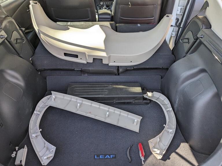
First, the part I was dreading, taking the entire rear hatch apart. :cautious:
KyDL4nN.jpeg


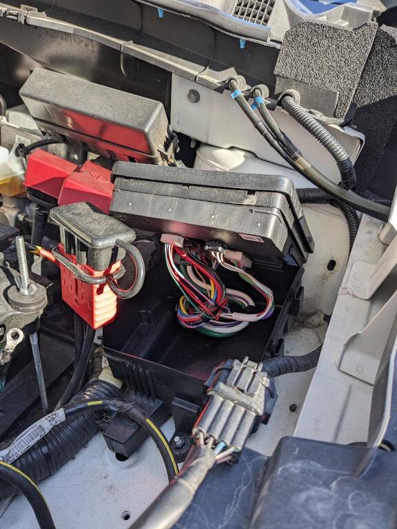
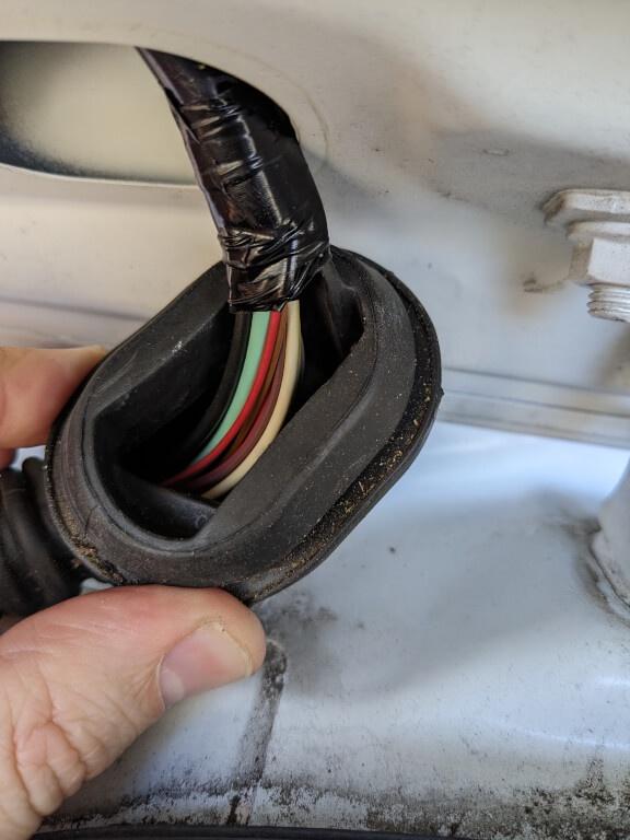
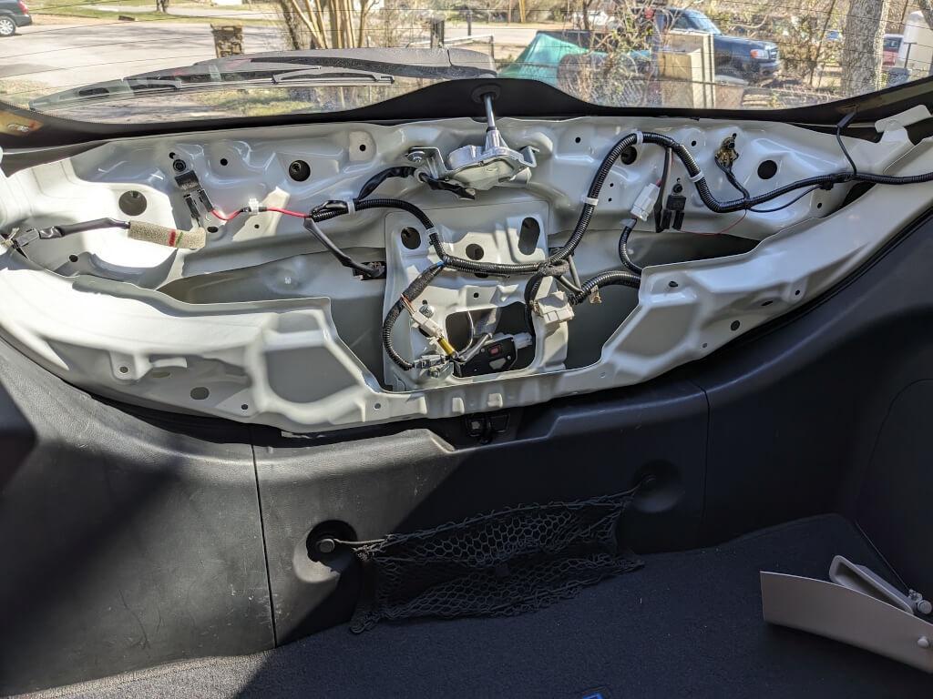
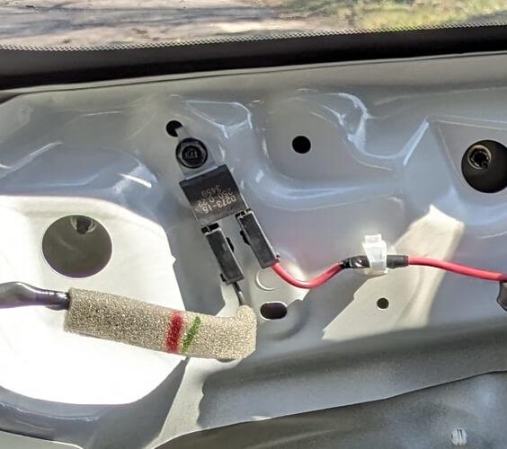
What the rear hatch looks like with all the plastic panels removed. I did notice most everything is connected to the door metal for negative, but then I also noticed the same central negative connect point also had another wire connected that would run back up the wiring to the front of the Leaf, so I'm guessing this is a redundant negative connection since the metal to metal connection is on a rotating hinge. To avoid sparks and / or welding while moving the door up or down, this was probably necessary. :unsure:
Zmg2JbC.jpeg


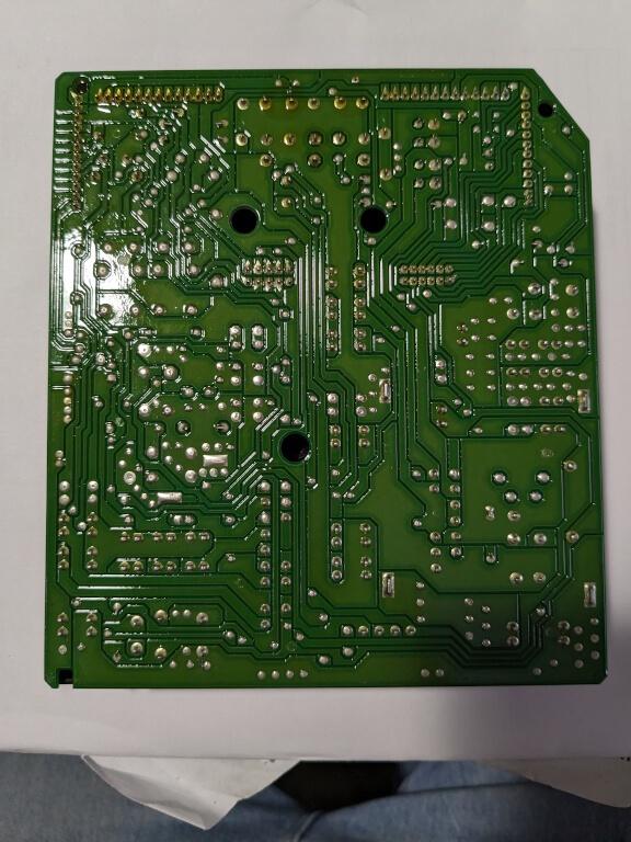
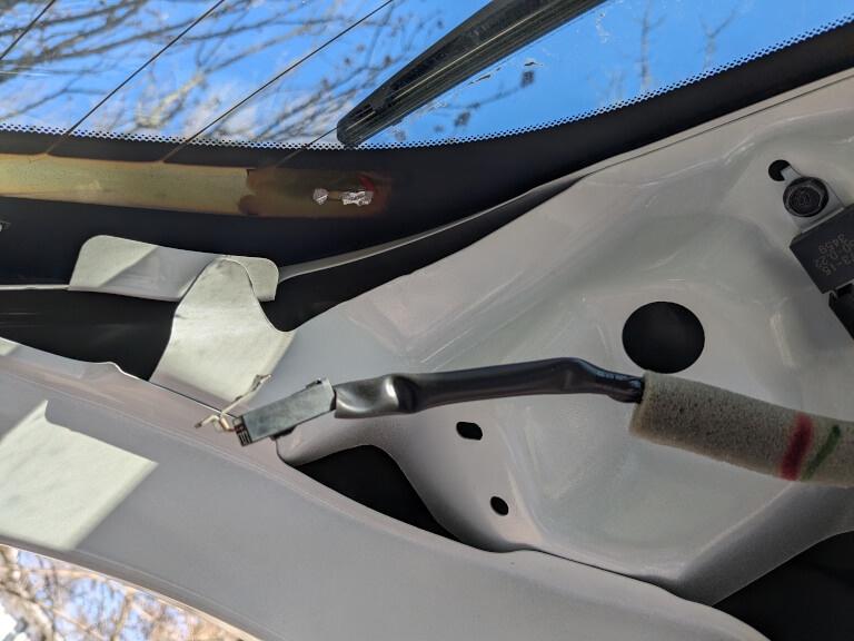
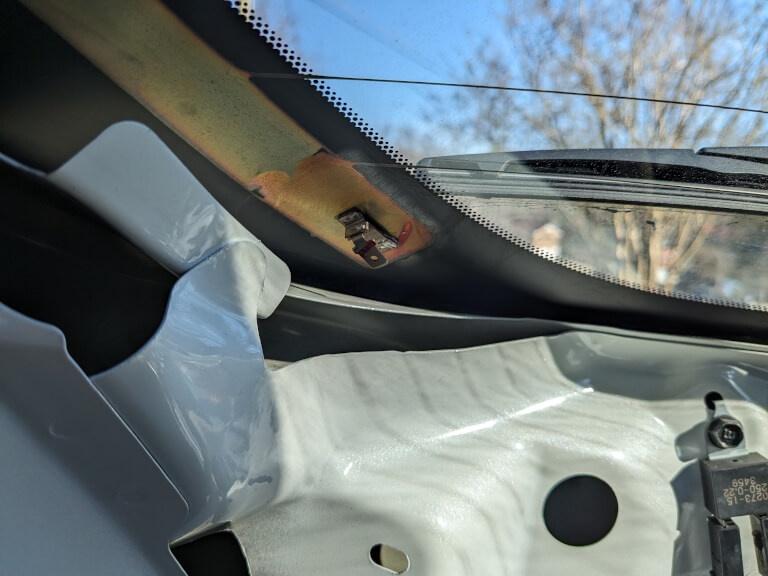
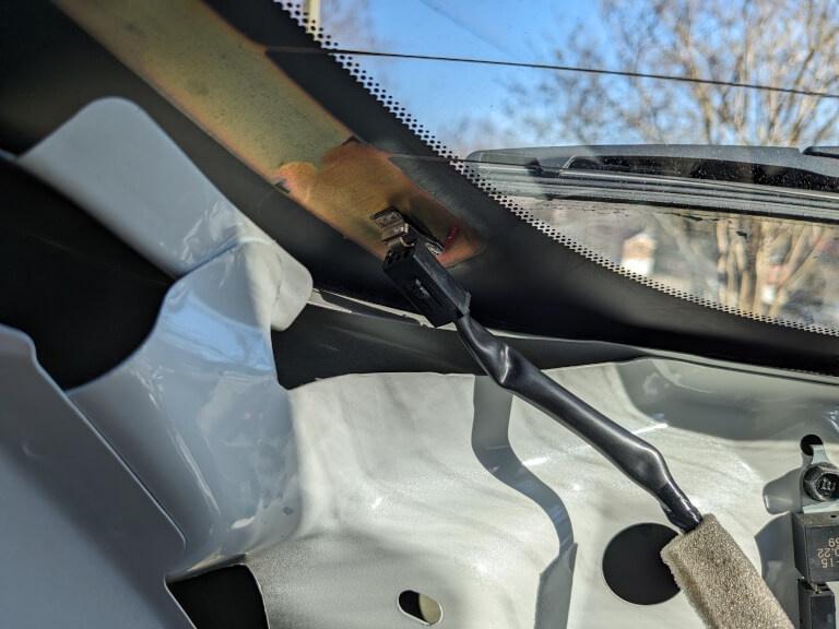
Finally, the moment of truth. The connector has broken off from the soldering points. 😵‍💫 Maybe I am slamming the rear hatch too hard? Well, I did check to make sure the break point wasn't because of melting, looks more like a sheer break. Maybe years of slamming the hatch or not enough solder at the factory? Either way, I have plenty of Solder I can use. :LOL:
jonI58C.jpeg


After carefully soldering the connector back into place and adding enough extra to hang a potted plant on :LOL: , I gave it time to cool down and set properly. Followed by some simple tap and movement test to make sure it wasn't just going to break off again immediately, everything looks solid.
mpx8YpF.jpeg


I plug the connector back in and do a couple of test with opening the hatching and slamming it shut to make sure it was going to stay, everything is still solid. I checked the other side to make sure I didn't see any cracks or if it was loose. Everything was quite solid on the other side. If it ain't broke, don't fix it. 🤨
1EruUmy.jpeg


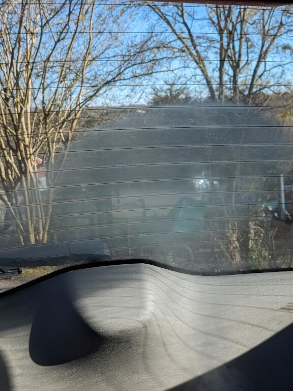
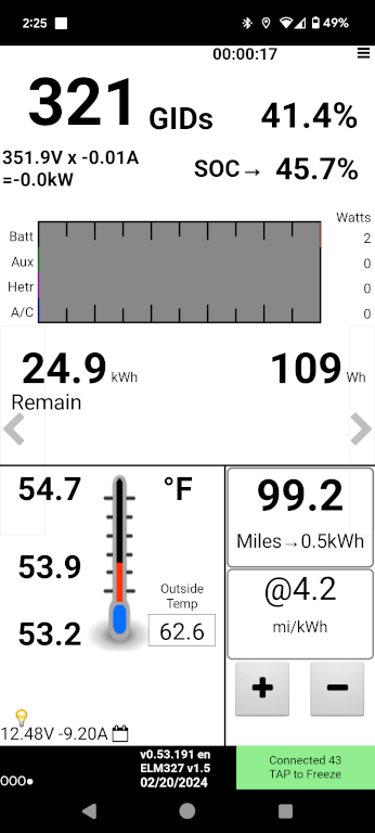
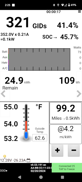
Next, fire up LeafSpy to see if it is actually using power to heat up. I first start with every possible accessory turned off in standby mode to get a baseline power reading. Then I switch on the rear defroster and immediately see the proper power draw. I give it some time to heat up and feel around the elements by hand. Everything is getting nice and toasty, hot. I switched the Leaf to "drive" mode and let the rear defroster run for another 10 minutes to make sure nothing was going to melt or burn; just in case. 😑
PYDkhwW.png

k200jUq.png


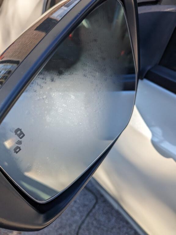
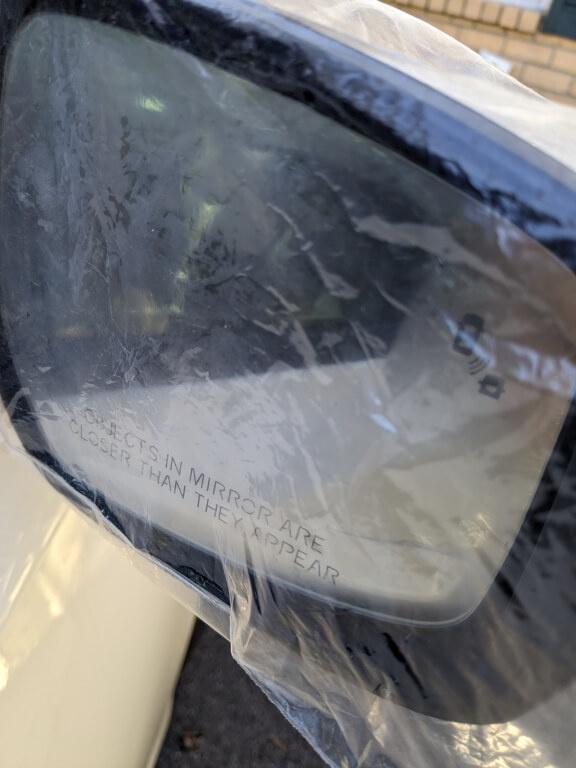
I believe my primary issue is solved. I put everything back together in the rear hatch. This still doesn't explain why my mirror heater on the drivers side does not work, but you know what? I will take the win for today on the rear defroster heating element. I'll save that mirror heater for another day. 😲
 
Last edited:
Nice fix :cool:
You must have a higher-wattage soldering iron? Can't see that a small one would have enough heat to do what you did.
Thanks for documenting your repair with some nice photos! I wonder what a dealer would have done......replace the whole rear glass :oops: you saved yourself some serious change!
40 watt setting was all it needed. I did use a hemostat to hold the connector and then another clamp to hold that hemostat in the correct position :LOL: so I could use two hands to do this. I couldn't do it with the hatch open in the air, so I had to fold down the rear seats, close the hatch, climb in the back, sit down and do the work in the closed position. Much easier. 😄

My guess, the dealership probably would replace the glass since it comes with the connectors already soldered to it, but if I could fix this with some simple (well I consider) electronics tools, I don't see why they couldn't either. But...as with any dealership, they want to make money, so yeah, order some new glass and charge a boat-load of money for labor. :cautious:
 
I notice in you last picture, I think you can see the capacitor I was talking about. That is where the manual said it should be.
Always a cringe worthy time, enough heat to melt the solder, not to much to crack the glass! Good going!
 
Is that a capacitor? I didn't notice. Wouldn't that block the current though? It's literally in line with the power feed.

Yeah, the next lowest setting I could use was 20 watts and I didn't think it would be enough. 40 watts was the next setting, so it was gamble to get that stuff to melt and pressed on as fast as possible. If I couldn't fix it and ended up breaking the glass, well was going to need new glass anyway, lol. 😄

Here is a zoom in on the section you mentioned:
1k0G1vZ.jpeg
 
Back
Top