Boards for lincomatic's open source "LeafCAN"

My Nissan Leaf Forum

Help Support My Nissan Leaf Forum:

This site may earn a commission from merchant affiliate links, including eBay, Amazon, and others.

chris1howell

Well-known member
Joined
Aug 10, 2010
Messages
649
Location
Lancaster, Ca
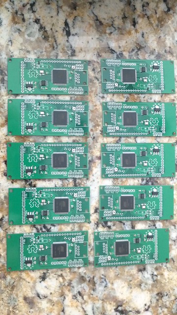
I just finished a batch of 20 boards for lincomatic's Open Source "LeafCAN". http://blog.lincomatic.com/?p=831
I will have boards for sale by the end of the week for $75 with US shipping and LeafCAN firmware loaded. Send a PM if you want one...

7965023072_fe7b7ae0f9_z.jpg


7998441494_f1b50e029e_z.jpg

Source code: https://github.com/lincomatic/LeafCAN

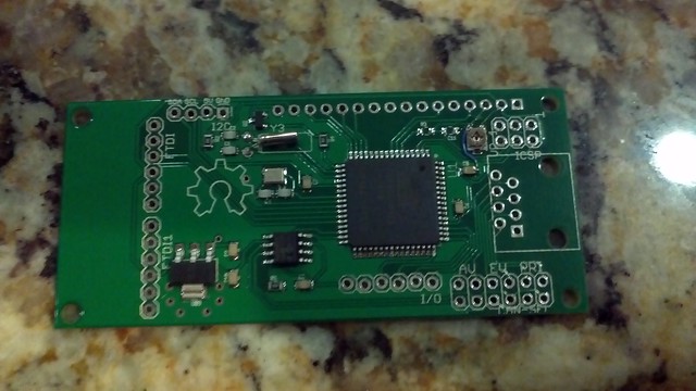
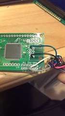
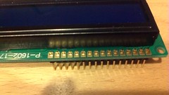
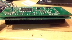
A basic build is simple and will take about 10-15 minutes. Just solder 4 wires from the OBD cable to the board, solder .1" header pins to the LCD and solder the LCD to the board...
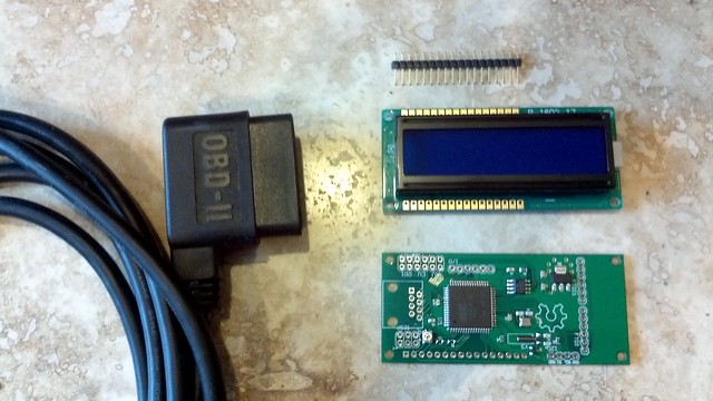
7998466071_644988c519_m.jpg
7998485471_7ab4d55536_m.jpg
7998465343_f94bb910f8_m.jpg


Parts required:
CAN board $75 - PM if you want one
OBD cable $12 http://www.obd2cables.com/products/...s/cable-j1962m-ra-type-b-to-open-end-6ft.html
LCD $4 -10 http://blog.lincomatic.com/?p=809https://www.adafruit.com/products/181
Enclosure $10 https://www.adafruit.com/products/903
Lincomatics 3D printed cases may be avaliable in the near future.

7998484369_36e4cd6e62_z.jpg
 
You can get a naked connector from Sparkfun for $3.95 and make your own cable. You only need 4 wires. Power, Ground ans the two can pins.

https://www.sparkfun.com/products/9911" onclick="window.open(this.href);return false;?
 
Is there a step-by-step procedure to compile modified firmware source
code, and load it into the micro-processor?

Can I make it easy to perform firmware updates in the field?

Thanks, Gary
 
The easiest way is to use AVRDude with a precompiled hex file. I sent you the hex and batch file earlier this evening. Just install AVRDude connect a ISP programer and run the batch file, in about 30 seconds the load will be complete.

To compile and load from source code, use the Arduino IDE setup with the AT90CAN files http://blog.lincomatic.com. Connect the ISP, select the AT90CAN board and click upload. You can use the resulting hex file later to program with AVRDude...
 
On the units I have constructed with the Sparkfun connector I exited the cables to the front of the car. I then covered the whole connector top with some paste like epoxy I have had on hand. The epoxy holds the wires and it insulates the terminals.
 
To re-program the board, does one need to solder
a 2x3 header into the ICSP holes?

What programmer do you use to plug into this board?
Link please?

My JTAG programmer (for the AVR-CAN board)
has a 2x5 connector, but you are not using JTAG.

Is your programmer called an "ISP" programmer?
Mine seems to have a 2x5 connector, as I recall,
but maybe I am confused.

Thanks.
 
garygid said:
To re-program the board, does one need to solder
a 2x3 header into the ICSP holes?

What programmer do you use to plug into this board?
Link please?

My JTAG programmer (for the AVR-CAN board)
has a 2x5 connector, but you are not using JTAG.

Is your programmer called an "ISP" programmer?
Mine seems to have a 2x5 connector, as I recall,
but maybe I am confused.

Thanks.

Nope, I use these solderless headers to program the boards. Without soldered headers the board\LCD combo is very slim.
https://www.sparkfun.com/products/10527

I use the Adrafuit programmer but many use the one from sparkfun. Both can program the 5x2 and 3x2 configuration. Your programer may also support 3x2.
https://www.adafruit.com/products/46
https://www.sparkfun.com/products/9825
 
I think I have the programmer from Sparkfun, or something
similar. I do not remember the 2x3 connector, but I will try
to find it tomorrow.

The solderless headers are the missing link, THANKS.

I appreciate your help.
I will send money tomorrow.
 
This is a surface mount rip off of the USBTiny. It is exact and the one I purchased works fine.

http://www.ebay.com/itm/300722516663?ssPageName=STRK:MEWNX:IT&_trksid=p3984.m1497.l2649" onclick="window.open(this.href);return false;
 
Chris, would you have any boards left from this batch? Please PM me if possible, I might be interested in purchasing more down the road.
1
 
Can anyone provide/link to assembly instructions? I think the only thing I need is the wiring for the ODB II cable to the board; the rest looks obvious.

Thanks
 
You might want to read the assembly instructions and
see the wiring diagram for the GID-Meter, at:
http://www.wwwsite.com/puzzles/socmeter/" onclick="window.open(this.href);return false;

Cheers, Gary
 
Got my LeafCAN board today and ordered the rest of the parts:

Yellow LCD - eBay per Lincomatic's blog (AdaFruit out of the one Chris linked to, plus Lincomatic says this one is easier to read)
Small Plastic Project Enclosure - Weatherproof with Clear Top - AdaFruit
Extra-long break-away 0.1" 16-pin strip male header (to mount LCD) - AdaFruit
OBD-II connector - SparkFun - I'll insulate the wire with silicon or something, will probably use ethernet cable (think I can find some stranded stuff at work).
 
Got mine today too. Does the schematic live anywhere? Is there another pad/place that would be good to attach the switched 12volt? I think I messed up mine when I was trying to switch wires. (Accidently put green/black instead of just green).

Here's the URL to Chris's flickr images blown up so you can see the wires better (Didn't find this until after things didn't work):
http://www.flickr.com/photos/60192309@N05/7998466071/in/photostream/" onclick="window.open(this.href);return false;
 
QueenBee said:
Got mine today too. Does the schematic live anywhere? Is there another pad/place that would be good to attach the switched 12volt? I think I messed up mine when I was trying to switch wires. (Accidently put green/black instead of just green).

Here's the URL to Chris's flickr images blown up so you can see the wires better (Didn't find this until after things didn't work):
http://www.flickr.com/photos/60192309@N05/7998466071/in/photostream/" onclick="window.open(this.href);return false;


Schematic is referenced on lincomatic's site and the final destination takes you to

https://github.com/lincomatic/LeafCAN" onclick="window.open(this.href);return false;

It's an Eagle format and you can download a free version of Eagle to view the schematic.
 
Nekota said:
Schematic is referenced on lincomatic's site

Yeah, but the github repo is out of date. It has firmware version 1.2 but the boards shipped with 1.3 and it's missing the actual board layout. I connected 12v to the regulator 12v pin and after more trial and error got things working! For some reason my backlight - pin didn't have ground, fortunately there was one near by.

Just some tips that are probably obvious:
Follow the images and don't sandwich the large OBD cable between the LCD and the board, it doens't fit well.
Obviously smaller OBD cable would be nice but the one linked was easy.
When testing it be careful, thankfully accidently shorting one of the unused wires just resulted in a fuse blowing.
Don't forget to adjust the potentiometer for contrast
If I'm understanding correctly the original schematic is setup to read the various canbuses by switching jumpers, these boards don't need any jumpering to read the EV bus though.
Don't mix up the color and color/black OBD wires
Lincomatics 3d printed case is a lot better fit than the project box linked.
Plan how your OBD cable is going to exit the box. Exiting out what turned out to be the right side and not the left side was a bad idea.

My understanding of the numbers displayed:
The top row is the remaining pack capacity/state of charge displayed in 4 different formats. KW/H, GID count, percent where 100% is 281 GID, and Lincomatics fixed fuel bar.
The second row has pack voltage, unknown number? and instantaneous watts (pack voltage * instantaneous amps)

Thanks Lincomatic and Chris! Now to ponder how I feel about 4.6% loss after 10.5k miles and 1.25 years.

 
Back
Top