OpenEVSE - Open Source Charging Station

My Nissan Leaf Forum

Help Support My Nissan Leaf Forum:

This site may earn a commission from merchant affiliate links, including eBay, Amazon, and others.
greenleaf said:
I received the OpenEVSE built by Glenn last Friday. He did a very good job.

I have a question regarding the DelayTimer.

This morning, I tested out the "delay charge" timer. I had set it to start at 22:00 and end at 06:00. At 6:30, I woke up to find the car still charging. I thought the OpenEVSE should have cut the charging at 6:00.

Existing Code
I looked at the code for DelayTimer::CheckTime(). The condition to stop charging is when (m_CurrTimeSeconds == m_StopTimerSeconds) is true.

Now, the definition of m_StopTimerSeconds and m_CurrTimeSeconds are

uint16_t m_StopTimerSeconds = m_StopTimerHour * 360 + m_StopTimerMin * 6;
uint16_t m_CurrTimeSeconds = m_CurrHour * 360 + m_CurrMin * 6;

Also, CheckTime() is set to execute by a timer interrupt every minute.

What I think happened
Because the condition to stop charging is checked by a timer interrupt, it is possible that the checking is missed at 6:00. For example, the two consecutive checks this morning could have been at 5:59:59 and 6:01:00. This misses 6:00.

What can be done?
If the above is true, then we can either

a) reduce the timer interrupt interval, say to every 55 seconds, or
b) change the check condition to
(m_CurrTimeSeconds == m_StopTimerSeconds) || (m_CurrTimeSeconds == m_StopTimerSeconds+6)

Another comment
It seems like the factor of 6 in m_CurrTimeSeconds is not needed since the seconds are never tracked. So the code could have been the following instead

uint16_t m_StopTimerMinutes = m_StopTimerHour * 60 + m_StopTimerMin;
uint16_t m_CurrTimeMinutes = m_CurrHour * 60 + m_CurrMin;

Any comments?
As an update to the above issue I reported, the main problem turns out to be not in the interrupt interval. Rather, the bug is in the condition that activates when the start and end times of the DelayTimer are set such that they straddle across midnight (e.g. 11pm to 1am). When the times straddle across midnight, the charging will not stop at the specified time.
 
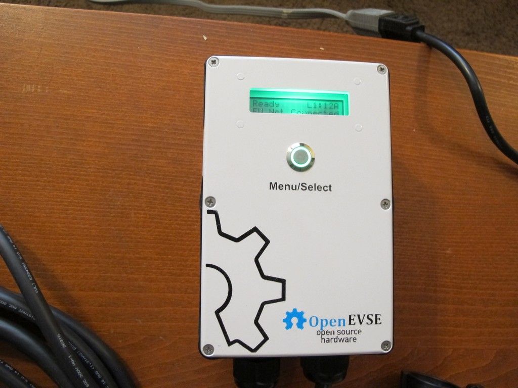
Chris Howell's new case arrived yesterday. Since he included weather seals I decided to make a weatherproof unit with a reflective display for outside use.

This consists of an OpenEVSE Plus board, 2 30A relays, Fuse block and fuses, cable glands, a diy display board with a status led glued to the center of the reflective display so it does not break the seal, a GFCI coil, input cable with a L6-20P plug, lighted push button, and a Leviton 15A cable from Amazon.

The J1772 cable is curious. It was sold as as a dual voltage cable. The current lines are green, red, and black. It seems to be intended for 240V use given the colors but the UL tag is for 120V. In any event for $99 it is a good deal.


GlennD said:
Chris Howell's new case arrived yesterday. Since he included weather seals I decided to make a weatherproof unit with a reflective display for outside use.

This consists of an OpenEVSE Plus board, 2 30A relays, Fuse block and fuses, cable glands, a diy display board with a status led glued to the center of the reflective display so it does not break the seal, a GFCI coil, input cable with a L6-20P plug, lighted push button, and a Leviton 15A cable from Amazon.

The J1772 cable is curious. It was sold as as a dual voltage cable. The current lines are green, red, and black. It seems to be intended for 240V use given the colors but the UL tag is for 120V. In any event for $99 it is a good deal.
Looks nice!
 
greenleaf said:
As an update to the above issue I reported, the main problem turns out to be not in the interrupt interval. Rather, the bug is in the condition that activates when the start and end times of the DelayTimer are set such that they straddle across midnight (e.g. 11pm to 1am). When the times straddle across midnight, the charging will not stop at the specified time.

Hi greenleaf. Were you able to resolve the bug? If you would like to report it (not resolved) you can report here: https://code.google.com/p/open-evse/issues/list

If you were able to modify the code to resolve the issue you can contribute your changes here:
https://github.com/lincomatic/open_evse or send me an e-mail at chris1howell83 at gmail dot com.
 
chris1howell said:
greenleaf said:
As an update to the above issue I reported, the main problem turns out to be not in the interrupt interval. Rather, the bug is in the condition that activates when the start and end times of the DelayTimer are set such that they straddle across midnight (e.g. 11pm to 1am). When the times straddle across midnight, the charging will not stop at the specified time.

Hi greenleaf. Were you able to resolve the bug? If you would like to report it (not resolved) you can report here: https://code.google.com/p/open-evse/issues/list

If you were able to modify the code to resolve the issue you can contribute your changes here:
https://github.com/lincomatic/open_evse or send me an e-mail at chris1howell83 at gmail dot com.
Chris, I have identified the fix but I haven't the chance to test it personally. I will update you after my test.
 
Well, I loaded your second fix on my test EVSE and at 5:30AM it was charging. As you can see it shut off properly


greenleaf said:
chris1howell said:
greenleaf said:
As an update to the above issue I reported, the main problem turns out to be not in the interrupt interval. Rather, the bug is in the condition that activates when the start and end times of the DelayTimer are set such that they straddle across midnight (e.g. 11pm to 1am). When the times straddle across midnight, the charging will not stop at the specified time.

Hi greenleaf. Were you able to resolve the bug? If you would like to report it (not resolved) you can report here: https://code.google.com/p/open-evse/issues/list

If you were able to modify the code to resolve the issue you can contribute your changes here:
https://github.com/lincomatic/open_evse or send me an e-mail at chris1howell83 at gmail dot com.
Chris, I have identified the fix but I haven't the chance to test it personally. I will update you after my test.
 
GlennD said:
Well, I loaded your second fix on my test EVSE and at 5:30AM it was charging. As you can see it shut off properly
Thanks.

It looks like I will not be able to receive the L6-30 plug by this weekend to make the 120V cable for me to test the OpenEVSE at my bench.
 
GlennD said:
Chris Howell's new case arrived yesterday. Since he included weather seals I decided to make a weatherproof unit with a reflective display for outside use.

This consists of an OpenEVSE Plus board, 2 30A relays, Fuse block and fuses, cable glands, a diy display board with a status led glued to the center of the reflective display so it does not break the seal, a GFCI coil, input cable with a L6-20P plug, lighted push button, and a Leviton 15A cable from Amazon.

The J1772 cable is curious. It was sold as as a dual voltage cable. The current lines are green, red, and black. It seems to be intended for 240V use given the colors but the UL tag is for 120V. In any event for $99 it is a good deal.

14 gauge wire in that cable. I wouldn't put over 15 amps through it.
 
The rating on the cable is indeed 15A but it works fine at 16A with no heating. Really 1A over is fine.

According to the table in my ARRL handbook the bundled current is 17A. Obviously the nec rating is 15A. Do as you please.
 
Locman emailed me to ask if I would build his OpenEVSE. He has had the parts for over a year so he had what was then recommended. Since he mounted the display before mounting the switch terminals I had to direct wire the push button switch. I think everything turned out fine. I will be getting it back to him next week.


waidy said:
What would it take to make an OpenEVSE that takes 3-phase charging? It's to be used in Hong Kong on a Model S.

The EVSE is not designed for 3 phase power. You would need a large transformer.

It will run on one of the three phases but it would not take advantage of the other phases. This could be a problem if the current on only one phase is limited.

I have ran my shop EVSE on both a 240VAC Delta and a 208VAC Wye. In both cases the panel breaker was 300A so I had no problem.
 
waidy said:
What would it take to make an OpenEVSE that takes 3-phase charging? It's to be used in Hong Kong on a Model S.
It's the car that would need to be designed for 3-phase charging. The EVSE can't make that happen. That said, I thought the Euro version of the car had 3 phase charging. Did they leave that out of the China model?
 
davewill said:
It's the car that would need to be designed for 3-phase charging. The EVSE can't make that happen. That said, I thought the Euro version of the car had 3 phase charging. Did they leave that out of the China model?
The Hong Kong Tesla Model S has 3-phase capability. Don't know about Mainland China Model S. Hong Kong is RHD (right hand drive); and Mainland is LHD (Left hand drive). Therefore, the model Ss in Hong Kong and Mainland will have at least that much different. Tesla will ship with a single phase box (not UMC) with delivery. They said their 3-phase box is under regulatory approval. It will be available once it's approved (god knows when).
 
What follows is engineering judgment based on what I've learned about the OpenEVSE design. But if you're serious about it, please verify this with Chris Howell before starting this effort.

If the Tesla accepts three phase-power, OpenEVSE could be adapted, but it would take a bit more hardware and a tweak of the software.

Obviously, you would need a third relay or a three-pole relay/contactor.

Doing it correctly would use three separate relays, three relay drivers and a third analog opto and port to test the third relay. It would also require an additional power-on test state, hence the need for software edits.

Three phase GFIC is also more complex. You will need a second-current sense coil and an additional filter/amplifier, either summing with the output of the first GFIC filter/amplifier or driving an independent comparator.

All of the parts would be there on two common OpenEVSE boards, so a clever tinkerer could lash together two boards to do the job. But that would not be a clean build. It would have many loose wires running between the boards. However, in the least, it would allow someone to prototype the concept before fabricating a custom board.

So it seems inevitable that three-phase OpenEVSE would require a new PC board with a few more inexpensive parts. The biggest added cost would be tooling the new board.

Bob

PS: Many thanks to Chris and the rest of the OpenEVSE team for a great job, start to finish.
 
waidy said:
What would it take to make an OpenEVSE that takes 3-phase charging? It's to be used in Hong Kong on a Model S.

OpenEVSE is compatible with 3 Phase Charging without modification. Simply use a single phase to power OpenEVSE, and a small 12v DC relay to switch the coil (also powered by a single Phase) of a 3 Phase Power relay. The voltage detect ICs can be connected to Phase 1 and 3 so you can have a different pilot setting for single or 3 phase. For GFCI you run each phase and Neutral through the OpenEVSE GFCI coil or use an External breaker with fault protection (may be required anyway depending on local requirements) with the OpenEVSE GFCI disabled (either in software or by not installing a GFCI coil).
 
Did I mention how much I love this project? ;)

I added a feature a few months ago that I couldn't live without today. A simple power meter that measures A and V. I saw a recent EVSE built by GlennD in the FS section and was reminded how useful a feature it is. Very simple to install, but I haven't measured its vampire draw.

You can buy them cheaply on eBay, but shipping may take some time since they're all coming from China/Hong Kong: http://www.ebay.com/sch/i.html?_trksid=p2050601.m570.l1313.TR0.TRC0.H1.X240V+dual+volt+amperage+meter&_nkw=240V+dual+volt+amperage+meter&_sacat=0&_from=R40" onclick="window.open(this.href);return false;
 
Back
Top