OpenEVSE - Open Source Charging Station

My Nissan Leaf Forum

Help Support My Nissan Leaf Forum:

This site may earn a commission from merchant affiliate links, including eBay, Amazon, and others.
Good evening. I want to make a resume of J1772-2010 and 62196/61851, please correct me if I'm wrong.

The Control Pilot circuit is the same for J1772-2010 and 61851. The difference is the Proximity part.

J1772

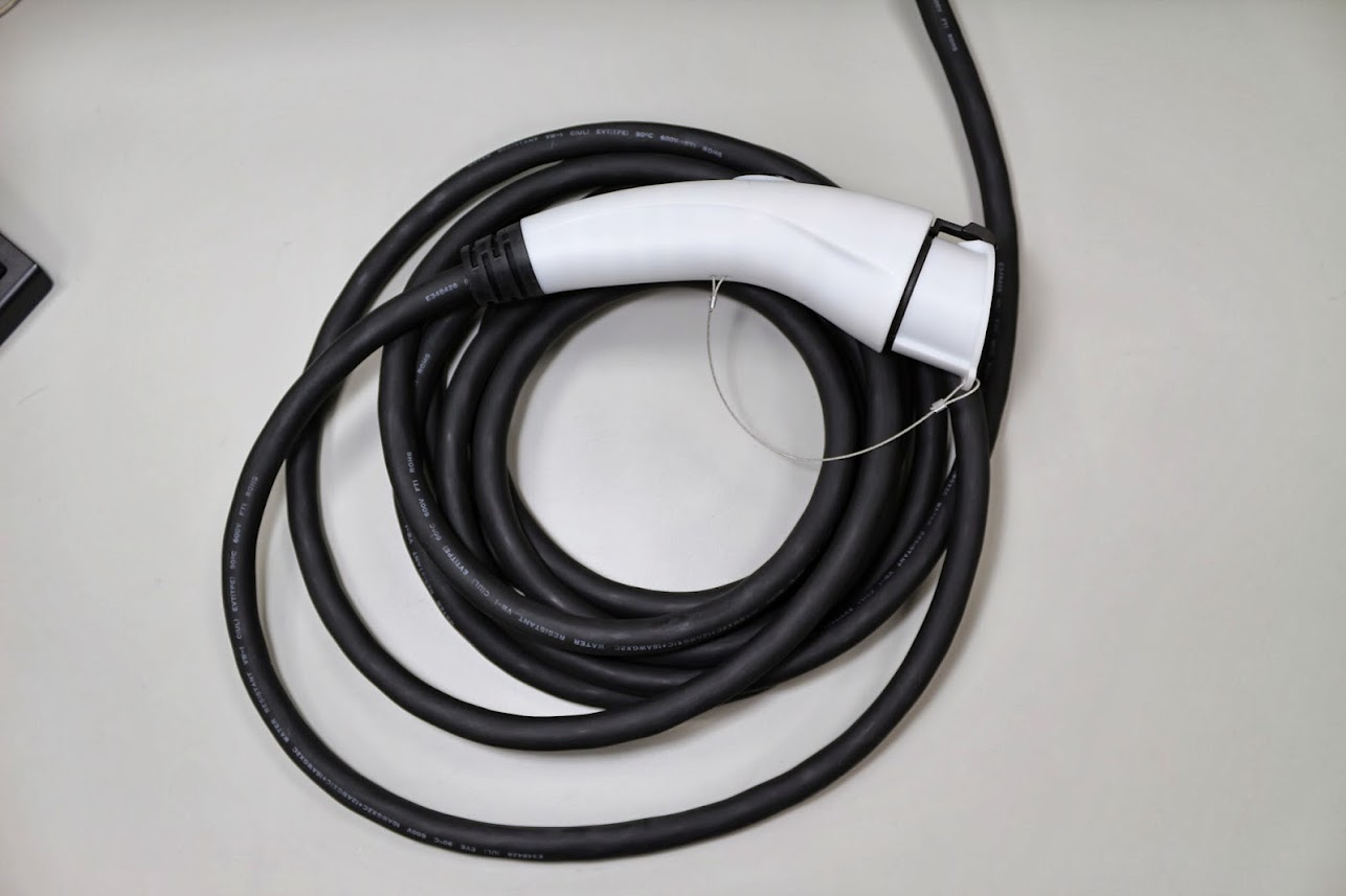
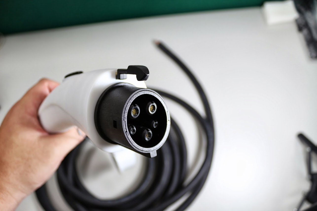
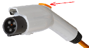
J1772 uses a Type 1 Cable, R6, R7 & S3 are intern in the J1772 plug/cable, R4 & R5 are in the vehicle (inlet). The EVSE outlet has a Pin for PP, which is normally not used. (?) The proximity part has 3 different states - Not connected, Button (S3) pressed & connected. This Button -S3 is the one marked on the following image: (?)
j1772plug7ey3o.png


This cable has no resistor that could be measured between PP & PE (like the Type 2 Mennekes cables) to define the cable's max. current. (?)


61851

This one uses a Type 2 cable or Mennekes-cable. There is a resistor between PP&PE, but not the resistances R4-R7 &S3 (like the J1772 cable). Here you can't push a button, so the EV changes it's state, but the EVSE-controller can "detect the maximum current carrying capacity of the connected charging cable. The charging output is only activated if the current carrying capacity of the charging cable is greater than or equal to the maximum charging current that is coded in the pilot signal." - Siemens.

- So if you want to use a Type2 cable, you have to make a part in the Open EVSE Code to measure the resistance from PE-PP.

PS:
00033552_0.png

This cable from Mennekes uses both 61851 and J1772-2010, on the left side you have a resistance of 680 Ohms between PP&PE, and on the right side, you have R6,R7 & S3 in the cable (R4&R5 are then logically in the EV) - the cable's max. current can be measured and you can press the Button -S3 to force the EV to change it's state.


Thank you for reading it, if you found something wrong, please let me know!
Greetings Chris.
 
ChrisM said:
- So if you want to use a Type2 cable, you have to make a part in the Open EVSE Code to measure the resistance from PE-PP.

Almost...

Currently, if you want to use a Type 2 cable, you have to verify the cable can handle the current yourself. If your cable handles less current than the pilot setting, you change the pilot. It is very easy if you have a LCD and push button.

If you want OpenEVSE to automaticly set the current for you based on the cable plugged in, then yes you would need to modify OpenEVSE and add the code.
 
chris1howell said:
ChrisM said:
- So if you want to use a Type2 cable, you have to make a part in the Open EVSE Code to measure the resistance from PE-PP.

Almost...

Currently, if you want to use a Type 2 cable, you have to verify the cable can handle the current yourself. If your cable handles less current than the pilot setting, you change the pilot. It is very easy if you have a LCD and push button.

If you want OpenEVSE to automaticly set the current for you based on the cable plugged in, then yes you would need to modify OpenEVSE and add the code.

Hi.

Well I want to make an EVSE that has relais for 3 different type2-cables: 13,20&32A. The PWM is always set to 32A or 53,33%. If a cable is connected that can't handle the 32A, for example a 20A cable, the EVSE measures automatically the resistance from PP-PE, and sets the PWM to 33,33% or 20A, and the EVSE controller will activate the 20A relais when the EV sets the state C. After the charging is done and the cable gets disconnected, the PWM sets itself to 32A again.

Thank you for your answers chris1howell, if you want, I or we could add you to the list "supporters" from our school project (We have to write something like a thesis about our EVSE.)

Greetings Chris.
 
I started stuffing the board before I downloaded the schematic. I made a few mistakes in the gfci circuit. Please do not go by my posted photo. After changing 3 resistors it works fine.

I can see why the gfci coil is so sensitive to placement, it is a very sensitive coil. I have a couple of TED current coils on hand and I thought I would use one. No chance, even with 200 ma unbalance it would not even register on pin 1.
 
ChrisM said:
... Well I want to make an EVSE that has relais for 3 different type2-cables: 13,20&32A. The PWM is always set to 32A or 53,33%. If a cable is connected that can't handle the 32A, for example a 20A cable, the EVSE measures automatically the resistance from PP-PE, and sets the PWM to 33,33% or 20A, and the EVSE controller will activate the 20A relais when the EV sets the state C. After the charging is done and the cable gets disconnected, the PWM sets itself to 32A again. ...
There would be no reason to have different relays. You only need one set that can handle the max amperage you want to support. Setting the pilot to the correct limit is all you would need to do.
 
davewill said:
ChrisM said:
... Well I want to make an EVSE that has relais for 3 different type2-cables: 13,20&32A. The PWM is always set to 32A or 53,33%. If a cable is connected that can't handle the 32A, for example a 20A cable, the EVSE measures automatically the resistance from PP-PE, and sets the PWM to 33,33% or 20A, and the EVSE controller will activate the 20A relais when the EV sets the state C. After the charging is done and the cable gets disconnected, the PWM sets itself to 32A again. ...
There would be no reason to have different relays. You only need one set that can handle the max amperage you want to support. Setting the pilot to the correct limit is all you would need to do.

I already thought about that, but I need 3 different circuit breakers. So how could it be possible to connect 3 different ones to one relais, and for example, if a 20A cable is connected, the other two circuit breakers (13 & 32A) are disabled(is that even possible or allowed?). This picture is from Siemens, they also use two different relais:

Schütz = relais
Leitungsschutzschalter = circuit breaker
siemens-cm230-13-32asfxz6r.png


Greetings Chris.
 
ChrisM said:
... I already thought about that, but I need 3 different circuit breakers. So how could it be possible to connect 3 different ones to one relais, and for example, if a 20A cable is connected, the other two circuit breakers (13 & 32A) are disabled(is that even possible or allowed?). This picture is from Siemens, they also use two different relais: ...
I guess I spoke too soon. A little searching around suggests that you're correct. The commercial implementations seem to use two sets of fuses, 16a and 32a, which would indeed require two sets of relays to match.
 
My 30A OpenEVSE unit is very similar to Rick Beebe's build and the workshop builds (from the OpenEVSE Wiki), esp wrt 30A fuses, NEMA L6-30 connectors, wire gauges, etc.

I had an electrician run 8AWG wire for the dedicated circuit, and a 40A fuse breaker; the circuit should be able to sustain 32A loads (80% of the 40A).

Is it safe to configure the OpenEVSE unit to 30A max current, or should it be set to 25A (to fall within the 80% rule for the components within the build)?

thanks
 
paulito99 said:
My 30A OpenEVSE unit is very similar to Rick Beebe's build and the workshop builds (from the OpenEVSE Wiki), esp wrt 30A fuses, NEMA L6-30 connectors, wire gauges, etc.

I had an electrician run 8AWG wire for the dedicated circuit, and a 40A fuse breaker; the circuit should be able to sustain 32A loads (80% of the 40A).

Is it safe to configure the OpenEVSE unit to 30A max current, or should it be set to 25A (to fall within the 80% rule for the components within the build)?

thanks

With the Nema L6-30 and 30A fuses you should set max current to 24A.
 
Hello.

Very nice project chris howell!

I have two questions, why can't i set the current higher than 80% of my circuit breaker or "GREATER THAN THE RATED VALUE OF THE EVSE", and why does the circuit breaker has to be rated at least 20% higher than the max EVSE current ?

thanks
 
Attempting to set the EVSE for currents higher than the capacity of it's components could lead to overheating, damage to the EVSE, and potentially a fire. For similar reasons, the National Electric Code does not want continuous currents in excess of 80% of the circuit's (breaker and wiring) rated capacity. Doing so for hours while recharging your car could overheat the less-than-perfect areas of the circuit such as connections and tightly-packed wire runs.
 
Wyatt said:
Hello.

Very nice project chris howell!

I have two questions, why can't i set the current higher than 80% of my circuit breaker or "GREATER THAN THE RATED VALUE OF THE EVSE", and why does the circuit breaker has to be rated at least 20% higher than the max EVSE current ?

thanks

It's 80% of the circuit breaker, which is 125% of the continuous current.

100 amp breaker = 80 amp continuous load = 20 amps less than the circuit rating, therefore 20 amps is 25% of 80 amps.
 
Hello.

Thank you for those 2 answers, i think i understood it now.


I also have trouble with the sensor reading part, I know that the -12V - +12V have to be transfered to 0 - 5V, so the Analog Pin can read it (it also can't read negative voltages).

On line 592, there are 5 different values defined:
THRESH_DATA g_DefaultThreshData = {875,780,690,0,260};

From line 308-312, States A->B, B-C, C->D, D and DS are defined.

Why is the 4th Number defined 0 (State D) ?

I really hope that you guys can help me, I appreciate it alot!
 
HankLeaf said:
VanceC that plug looks like made for simplicity, is it certified :?:
And have you used it already :?:
Well it's well suited for it's price, I was looking for a reasonable aftermarket plug anyways.
And I checked with my friend, it is certified.
 
@ chris howell

Why do you need 2.4k resistors for the DC/DC converter (I know that the datasheet says that you need the 1µF capacitors, but it says nothing about resistors)?


Thanks and Greetings
 
Hi everyone,
I just found an EVSE that is basically in the J-1772. I wonder if we can make an open EVSE and stuff the board/relay into the handle like this. I remember Chris made some all in one boards with 20A relays (I bought one) and I wonder if this can be done.

IMG_6558_500x333.jpg


http://www.charge-amps.com/um-evse" onclick="window.open(this.href);return false;
 
Hello Chris and others,
Just wanted to post that I have finally begun my Open EVSE build. Made some good progress today, got all the soldering done, fabricated the mounting plate for the enclosure and completed the mechanical assembly. Just need to finish the AC wiring and fire it up for testing.

10/2/13
Picture removed - Photobucket sucks
ON EDIT 10/3/13: It lives, there is some overshoot (or sag maybe) in the pilot signal. You can see the curve on the scope. Not sure how the Leaf will react to that. Next step is plug it into my Leaf........... as soon as I get the supply cable hooked up.
Picture removed - Photobucket sucks
EDIT: Here it is hanging on the wall next to the blink........waiting..............
Picture removed - Photobucket sucks
EDIT: Starting it's first charge session from LBW on my Leaf.
Picture removed - Photobucket sucks
 
Back
Top