OpenEVSE - Open Source Charging Station

My Nissan Leaf Forum

Help Support My Nissan Leaf Forum:

This site may earn a commission from merchant affiliate links, including eBay, Amazon, and others.
gobble said:
TonyWilliams said:
What do you think blue is?

I don't know what blue is, but I don't think it's the pilot based on these instructions in the how-to:

2.Cut the blue wire short, bend 180º and insulate by covering with electric tape. It is not used.
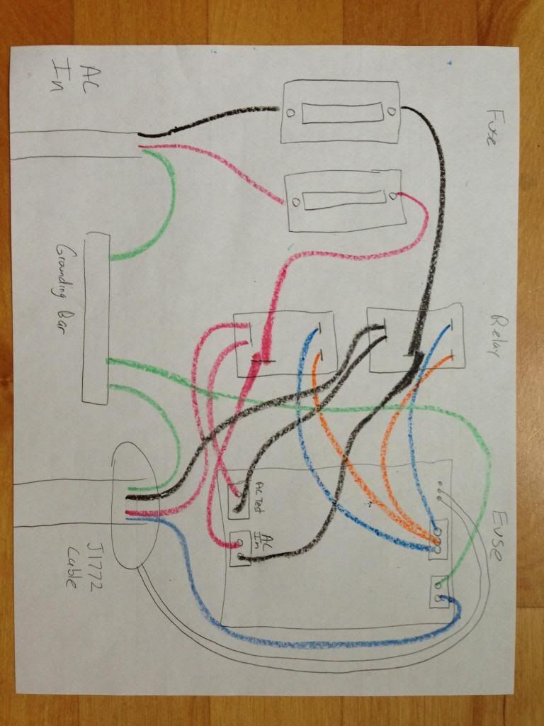
The color of the pilot wire is not standard. For the Leviton J1772 cable, it is orange. For your Voltec J1772 cable, it sounds like it is blue.

Cheers, Wayne
 
Leviton is one of a few cables that has 5 wires giving access to both the pilot and proximity pin. Most cables have just 4. Blue is a common color for pilot, but it is orange on leviton.
 
So it sounds like if I hook up the blue to pilot I'll be charging high speed. I'm close to being done.
 
Well mine doesn't work. I plug it in and the green light on the button turns on and that's about it. When I press the button the LCD changes colors but no writing on the LCD. The car says charge cord plugged in but it's not recognizing it in any other way. I don't even know where to start with troubleshooting other than to recheck all the wires and connections. Anyone have any ideas?
 
gobble said:
Well mine doesn't work. I plug it in and the green light on the button turns on and that's about it. When I press the button the LCD changes colors but no writing on the LCD. The car says charge cord plugged in but it's not recognizing it in any other way. I don't even know where to start with troubleshooting other than to recheck all the wires and connections. Anyone have any ideas?


First adjust the contrast pot on the lcd logic board. Then you will be able to read the specific error.

Most common problem is all grounds are not tied together. Ac ground, J1772 ground and OpenEVSE ground should all be tied together.
 
chris1howell said:
Leviton is one of a few cables that has 5 wires giving access to both the pilot and proximity pin. Most cables have just 4. Blue is a common color for pilot, but it is orange on leviton.

The pilot is purple on Tesla, and blue is proximity (yes, I wired the first one backwards).

Normally, you wouldn't have any need for a proximity conductor since the switching and "logic" for the proximity is normally all within the J1772 plug.

Tesla uses the proximity to send 3 volt power for the remote plug unlock, hence the need for the conductor. Tesla also uses a "pilot" signal from the wall power plug (at the NEMA 14-50, et al plug) that tells the EVSE how many amps is maximum to pull from the wall.

For instance, with a 14-50, it will pull 40 amps (80% of 50 amps), but a NEMA 14-30 plug will only allow 24 amps (80% of 30 amps).
 
MashedPotato said:
I've been using the Open EVSE that many of us made at the workshop a while back, but it needed to be re-flashed before I could use the button to change settings. I finally got it going today and am posting the steps I went through this morning. (I missed the workshop yesterday.)

- Purchased USBasp programmer and downloaded Windows driver. Programmer came with 10-pin connector, so I made a new cable to connect to the Open EVSE board's 6-pin programmer port.
- Installed Arduino IDE.
- Downloaded Time and LiquidTWI2 libraries and extracted each into their own folder in arduino\libraries
- Downloaded Open EVSE firmware and opened in Arduino IDE.
- In Arduino IDE, set programmer as USBisp under Tools->Programmer, then used the option to "Upload using programmer".


Thanks ;)
 
Hello chris1howell

I'm testing with "Arduino 1.0.5" while I get the order.

My installation already has GFI protection (40A 30ma), and I would like to off the GFI

I modified the next line
//# define GFI

But when compiling I get this error:
'GFI_TIMEOUT' was not declared In this scope

How I can fix it?

You can override the two contacts with a 10k resistor as I read somewhere?

The option I chose Programmer
Tools> Programmer> USBasp

What card you have to choose from the menu Tools> Board ?
Arduino Mini w/ATMega328 ?

Thanks
 
chris1howell said:
gobble said:
Well mine doesn't work. I plug it in and the green light on the button turns on and that's about it. When I press the button the LCD changes colors but no writing on the LCD. The car says charge cord plugged in but it's not recognizing it in any other way. I don't even know where to start with troubleshooting other than to recheck all the wires and connections. Anyone have any ideas?


First adjust the contrast pot on the lcd logic board. Then you will be able to read Tesla error.

Most common problem is all grounds are not tied together. Ac ground, J1772 ground and OpenEVSE ground should all be tied together.

My error is:

EVSE Error
Stuck Relay

I can't figure out how to post a picture I drew of my wiring. Looks like this forum requires it to be hosted somewhere else.
 
Here is my wiring. Does anyone see any errors?

evsewiring.jpg
 
TonyWilliams said:
For instance, with a 14-50, it will pull 40 amps (80% of 50 amps), but a NEMA 14-30 plug will only allow 24 amps (80% of 30 amps).
I am a little confuse. NEMA 14-30 requires a 40Amp breaker. Doesn't a NEMA 14-30 plug allow 80% of 40 Amp (i.e. 32Amp max)?
 
waidy said:
TonyWilliams said:
For instance, with a 14-50, it will pull 40 amps (80% of 50 amps), but a NEMA 14-30 plug will only allow 24 amps (80% of 30 amps).
I am a little confuse. NEMA 14-30 requires a 40Amp breaker. Doesn't a NEMA 14-30 plug allow 80% of 40 Amp (i.e. 32Amp max)?

I believe the NEMA nomenclature specifies the max amps as the 2nd number, so NEMA 14-30 is rated for 30 amps
 
The most simple way is just to remove the Current Transformer.

Roberto33 said:
Hello chris1howell

I'm testing with "Arduino 1.0.5" while I get the order.

My installation already has GFI protection (40A 30ma), and I would like to off the GFI

I modified the next line
//# define GFI

But when compiling I get this error:
'GFI_TIMEOUT' was not declared In this scope

How I can fix it?

You can override the two contacts with a 10k resistor as I read somewhere?

The option I chose Programmer
Tools> Programmer> USBasp

What card you have to choose from the menu Tools> Board ?
Arduino Mini w/ATMega328 ?

Thanks
 
chris1howell said:
gobble said:
Here is my wiring. Does anyone see any errors?

evsewiring.jpg

I Love the drawing!!!

It looks perfect. With no power on check both relays with a ohm meter, they both should be open. It is possible you could really have a stuck relay.

Chris, do you seriously think wax wires can handle that much current?
 
chris1howell said:
gobble said:
Here is my wiring. Does anyone see any errors?

evsewiring.jpg

I Love the drawing!!!

It looks perfect. With no power on check both relays with a ohm meter, they both should be open. It is possible you could really have a stuck relay.

I'm up and running now. I took apart and re-wired based on the new picture Chris has on the Google site. I must have had a wire crossed somewhere. If that's the case this thing has some good safetys programmed into it.

Thanks to Chris for answering all my dumb newbie questions!
 
Hello Guys.

I have a question about the "Proximity" part:
In this tutorial I saw how the Pilot circuit was done, and i also found it in the Open EVSE Source Code. But J1772 also includes a proximity circuit.
(http://en.wikipedia.org/wiki/SAE_J1772#Signaling" onclick="window.open(this.href);return false;). So there you have different resistances between PP & PE. Now i want to know, is this also included in
the Open EVSE Code? If so, please be so kind and show me this part please.

I hope that you can answer my question,
Kind Regards

Chris M.
 
Back
Top