Building a Timer for my EVSE

My Nissan Leaf Forum

Help Support My Nissan Leaf Forum:

This site may earn a commission from merchant affiliate links, including eBay, Amazon, and others.
LEAFge15313PrintedCircuitBoard_zpsa6b1a115.jpg


49DA3648-F5E6-446D-9683-83B234D19CF4-13585-00000963A21C8E5B.jpg


E697E1AE-840A-4D3F-B2B6-FC5C1F4280E6-13585-00000963A6428F45.jpg


FA8F86CC-0D0B-4AB7-A606-782F62A5F9A5-13585-00000963A443B691.jpg
 
hgoudey said:
I don't want to spoil the fun of hacking your existing timer to work in your application...

Oh, Phil and I are thinking about a really big time waster some day soon... just for our own curiosity.

The Intermatic FM1D20-240U is a newer, slicker looking version, but the override button looks tiny and it is also pricier at $110.

No backlight, either? Crap, for that kind of money, I'm sure there are other choices. I couldn't tell if there was a straight NO/NC switch (well, I need NO).
 
I still can't see the traces behind that supercap. I have everything else already. My guess is the Anode of D2 connects to the trace that leads to the blue wire on the digital board. D3 is for the supercap?

Can you power up the unit on a 120v load and carefully measure DC volts? Connect the positive meter lead connected to the Blue AC wire, and then probe the White, Blue, and Grey small wires leading to the digital board.

-Phil
 
Ingineer said:
I still can't see the traces behind that supercap. I have everything else already. My guess is the Anode of D2 connects to the trace that leads to the blue wire on the digital board. D3 is for the supercap?

Yes, D3 goes to C13.

But, D1, D2, and D3 are all in series. At the connection of D3 and D2, that lead goes up to Q3. Hopefully this pic can help:


282AA7AC-ACA7-471E-A649-A71600C58A6B-13585-0000096EC922C6B3.jpg


Can you power up the unit on a 120v load and carefully measure DC volts? Connect the positive meter lead connected to the Blue AC wire, and then probe the White, Blue, and Grey small wires leading to the digital board.

-Phil

Tomorrow.
 
Ok, now as soon as I know the voltage of that Zener (you'll tell me when you take the readings), and how the Clipper Creek enable line works, I can tell you how to hook this up directly. (Probably without needing any additional components.)

I'm going to guess 5V on blue, near 0V on white (after power-on reset), 0v on red (should be the same as your positive meter connection), and grey will depend on whether the timer is in "on" mode (0v) or "off" (5v).

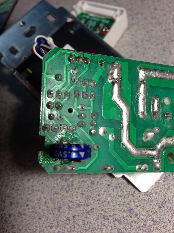
If true, All you need to do is some simple soldering and locate the 5V source in the clipper creek, or use a 5v wall-wart. A picture of the CC PCB would be helpful too!

If the CC enable line is "ground to charge", then it's super-simple.

-Phil
 
Back
Top