120-to-240 Adapter Kit (Rev 1)

My Nissan Leaf Forum

Help Support My Nissan Leaf Forum:

This site may earn a commission from merchant affiliate links, including eBay, Amazon, and others.

garygid

Well-known member
Joined
Apr 21, 2010
Messages
12,469
Location
Laguna Hills, Orange Co, CA
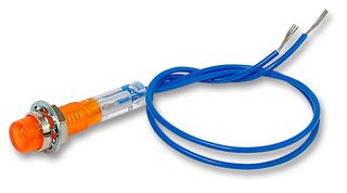
This first post is an incomplete overview of the "120-to-240 Adapter Kit" (Rev 1), including a simple Neon 240v-Present Indicator, but no Buzzer.

The main wiring and the use of two AC 120v-coil relays for safety has few options.

------------
NEW: The "240-Stubby" version uses an output "pigtail" with an in-line L6-20R connector ... instead of a wall-socket L6-20R "inside" the box.

-----------
The next post will contain a detailed Parts List for this specific Kit and links to most sources.

The 3rd post is possible Assembly Instructions for the Kit.

The 4th post will cover Tools, etc.

LEGAL WARNING: Use the information in this thread ENTIRELY at your OWN RISK. There might be mistakes or omissions. If you are not competent to evaluate AND attempt this project, get professional help.
 
Parts List for 120-to-240 Adapter Kit (Rev 1): (not yet complete)

("240-Stubby" uses a pigtail with a molded, in-line L6-20R rather than a wall-socket L6-20R.)

1. Project Box: a standard 2-wide? electrical enclosure/junction box, plastic.
Mayby 1-wide will be sufficient for "Stubby".

2. Receptacle: L6-20R, it should include mounting screws. For "Stubby", use an L6-20R "pigtail" instead.

3. Cover for box (#1) with circular cutout for the socket (#2). "Stubby" does not require the socket-mounting hole. It should include mounting screws.

4. 120v Connection Cords: Two short cords (very short for "Stubby"), or one short and one long, with a molded 5-15P connector, round cable, at least 12/3 wire, suitable for at least 16 amps. Stubby might "allow" 14/3 wire, since the stubs are only a few inches long. We will just use the male 5-15P ends for this project.

5. Relays: Two 120v AC coil, ... I will copy link and part number from other thread. About $6 to $10 each.

6. Spade Lugs: We need ten, four to connect to each of the two Relays, and two to connect the In-to-Out Grounds.

Note: Two different spade sizes (six 0.250 and four 0.125) are probably needed (check the selected Relays). Also, crimp-tubes sized for the wires being used: three bigger to crimp two incoming-size wires, 7 medium to crimp one I/O wire.

7. 240v Neon Indicator: With resistor, already in through-panel housing, with two wires attached. Just over $2 ($2.22).
http://www.newark.com/jsp/search/productdetail.jsp?SKU=70C1382&CMP=AFC-GB100000001

8. Wire: Two 4-to-6-inch pieces of insulated, stranded wire (like the "input" wire. Then, (not needed for "Stubby"), two 6-inch pieces of insulated, solid, 12-gauge wire.

9. Through-wall cable clamps: Two (three for "Stubby") circular "waterproof" cable gasket/clamps, to fit the two Input (and one Output, for "Stubby") cords being used. About $3 each?

NOTE: No solder necessary, all connections are crimped with insulated connectors.
 
Assembly Instructions: (not yet complete)

(In some version of the Kit, some of these
steps might already be completed.)

1. Punch (or drill) two holes for the 120v cords to enter the box
(for "Stubby", one more to exit the box), through suitable circular
cable clamps. Install the 2 (or 3) clamps, loosely.

2. If needed/desired, holes for mounting the 2 Relays. Most likely one relay
will fit on either side of the L6-20R receptacle. For Stubby, the two relays can probably fit in a smaller box, if desired for compactness.

3. Drill a hole, probably in the side of the box (top for Stubby) for the Neon Indicator housing. Make sure that there is sufficient clearance inside the box, around the other components, for the "long" body of the Indicator.

4. 120v-Input Grounds: Connect both together to the Green terminal of the L6-20R socket. For Stubby, the two grounds crimp into one female spade lug, and the outgoing Ground crimps into a mating male spade lug.

5. 120v-Input Neutral Leads: Strip and crimp on (securely) an insulated female "narrow" spade lug. Connect the spade lug to one side of the Relay Coil.

6. Do the same (#5) with the other 120v-Input Neutral wire.

7. 120v "Hot" Lead: It goes two places: indirectly to one side of the relay coil (low current) and directly to the N.O. (Normally Open) contact of the Relay (high current). Strip and put the "Hot" wire AND a the short, similar wire in a suitable insulated female "wide" spade lug, and crimp securely. This lug plugs onto the N.O. Relay contact. Crimp a 2nd "narrow" lug onto the other end of the short wire, which plugs into the remaining Relay-Coil contact.

8. Do this again (#7) for the other 120v "Hot" wire, connecting to the other Relay.

9. Using a short piece of suitable insulated Solid wire, strip both ends, one end suitable to attach to a "Hot" terminal on the L6-20R socket, and the other end suitable for a "wide" Female Spade Lug. (For "Stumpy", use the stripped end of the outgoing wire.) Add one of the small-gauge "240v Indicator" wires to this wire in the crimp-barrel of a "wide" spade Lug, then crimp them securely, and plug the spade lug onto the "common" contact of the Relay.

10. Do the same thing (#9) with the other Relay and remaining 240v Indicator wire.

11. Adjust the components, cables, and connections into their final positions. Tighten the two (three for "Stubby") cable clamps to SECURELY hold the cables in place.

12. Double-Check every connection very carefully, for correct placement/connection, solidity of the crimp and spade connection, and that parts inside the box CANNOT touch anything that they shouldn't touch.

13. Cut a suitable hole (probably 1 and 9/16 inch diameter), if necessary, in the "lid" of the box. (Not necessary for "Stumpy".)

14. Securely connect the L6-20R receptacle's 2 "Hot" wires, and mount the socket in the box. (This step is not needed for "Stumpy".)

15. Mount the Lid.

16. Test ... CAREFULLY.
 
Tools: (incomplete)

1. Screwdriver(s):

2. Crimp Tool: Inexpensive at Lowes or similar hardware store.

3. Wire Stripper:

4. Pliers: ...

5. Hammer: ...

6. Drill: Drill motor and drill bit to make hole for Indicator mounting,
and possibly some holes for mounting the two Relays.
 
How about using a neon lamp instead of an LED? No messy diodes & resistors to deal with. Just plug n play. For instance:

http://www.skycraftsurplus.com/250vneonpanellampsindicatorlampspilotlamps.aspx

You can get them in all shapes ... maybe a round one would be easier to install.
 
I used one 25ft extension cord, cut it in half and replaced the female connector with a 5-15p. I used a 4X4X2 PVC junction box from Lowes for the enclosure. Ill post my parts list, links and some photos later. Total cost was around 60 dollars. I had to drill two 3/4" holes for the cord grips, a 1/2" for the neon pilot light and a 1.5" hole for the L6-20.
 
img20110708223430.jpg

img20110708223105.jpg

img20110714194753.jpg
 
Relays Part#G2813395 [email protected]
http://www.zorotools.com/g/Enclosed Power Relays Magnecraft/00062830/

Cord grips Part#G1448212 [email protected]
http://www.zorotools.com/g/00058757/k-Compact Nylon Multicord Grips/

Pilot light Part#G2854607 [email protected]
http://www.zorotools.com/g/Indicator Lights/00055114/

I bought the enclosure from Lowes. SKU#10008 [email protected]

Extension cord from Lowes. SKU#242127 [email protected]

Steel locknuts from Lowes. SKU#75443 [email protected]

5-15p from Lowes. SKU#164829 [email protected]

L6-20r from Home Depot. SKU#616068 [email protected]
 
I couldn't wait and ordered a Quick220 a while ago already. But I want to mention that the Quick220 has an "on/off" switch that looks like a circuit breaker type switch on the side. I asked them what it's for and they said it's a safety switch in case you connect to a device that's an instant current draw. That way you won't have to deal with a spark at the time of plug in. You can make sure the switch is off, plug in, then turn the switch on, and won't get a spark at the plug.

I don't think it's necessary for the purpose of the EVSE connection because there's a handshaking going on first with the pilot signal and all. But if you intend to use it for other things beside the EVSE that may produce a spark at connection time, it may be worth considering installing the switch.

The Quick220 people told me that the switch they use is a heavy duty switch intended for life long operation and can cost as much as $75 retail price.
 
Nice list, Thanks.
It starts to look like it is difficult to provide a cost-effective kit, considering that the parts buyer might be stuck with excess inventory.

I get about $72 (plus shipping and sales tax) for these parts.
(Plus some Spade Lugs.)

One needs a Crimp Tool, and a "special" drill bit, at least for the large hole.

If one uses moulded "pigtails" for the two 5-15P and the L6-20R (instead of a socket), then the labor is noticably less, the parts are only slightly more, and the extension cord remains intact as an accessory. Just a thought.

Suggestions?
 
Volusiano said:
I couldn't wait and ordered a Quick220 a while ago already.
Real close to following your lead--I have not gotten around to even going to the vendors... All good learning but maybe your move saves time for the fun of driving the LEAF! Anyway, I am in for seeing how a kit could be done, hope that the one who does the work and shipping could factor in something for their troubles.
 
garygid said:
If one uses moulded "pigtails" for the two 5-15P and the L6-20R (instead of a socket), then the labor is noticably less, the parts are only slightly more, and the extension cord remains intact as an accessory.
This is what I did when I built mine. I think using an L6-20R at the end og a short cord, rather than one built into the box, may be a little easier to deal with in-use. I actually did not use a molded pigtail; I used a Leviton connector I bought from Ebay.
 
garygid said:
Nice list, Thanks.
It starts to look like it is difficult to provide a cost-effective kit, considering that the parts buyer might be stuck with excess inventory.

Suggestions?

I think you're right. Now that we have a pretty good idea of what parts are needed; where they might be obtained; and a very nice write-up of how to assemble for those who need it (and thanks for doing that Gary!), I think we should let folks do their own thing.
 
garygid said:
It starts to look like it is difficult to provide a cost-effective kit, considering that the parts buyer might be stuck with excess inventory.

Suggestions?
What if you bought enough parts for say 10 kits at a time - and wait until you have interest for 10 kits before you order the parts. That should minimize excess parts and shipping overhead on the parts-buyer.
 
It's possible, but there is a lot of time involved, even if you have a Lowe's parts number for a piece.

I might make/describe/offer another project/kit called "240-Stubby" with no socket:

1. 3 Pigtails and 3 Cable Clamps
2. 2 Relays
3. 1 Box and Cover, and 1 Neon Indicator
4. and 10 crimp spade lugs, one male

The labor will be less.
The long extension cord will be an "extra".

-------
Of course, my super-stubby "120-Joiner" is even easier, but lacks the safety feature that the Relays provide. :D
 
As you're putting the parts list together, note that the relay contacts require .250 quick-connect terminals, whereas the relay coils terminals are .157 quick-connect. Not sure if anyone has noticed this yet... You'll need four yellow .250 quick connects for hooking the 12 AWG wires to the relay contacts, two yellow .157 quick connects for hooking the neutral wires to the relay coils, and two red .157 quick connects for jumping from the other coil contact to the hot side of the input. (All female quick connects) Only the barrel of the quick connect needs to be insulated thanks to the way the terminals are recessed into the top of the relay case. As a matter of fact, certain fully insulated quick connects have a "bump" in the insulation which might prevent them from being plugged into the relays.

You'll also need a way to connect the 3 ground wires together; I used a push-in thingy I got at Home Depot, but was not entirely happy with the results; it would have likely worked much better with solid wire.

I ended up with blue .157 quick connects which I picked up a Pep Boys Automotive, which are too small for 12 AWG wire. As a matter of fact, I used blue .250 quick connects also, because I had them in my junk box.. This meant that I had to use short 14 AWG THHN stranded jumpers for the quick connects, which I spliced to the 12 AWG stranded conductors from the SJOW pigtails using yellow crimp-on butt splices (6 were required).
 
Back
Top