49thdiver
Well-known member
I have posted the complete solution on page 17 post #164. Thanks to everyone, good luck with your projects.  https://mynissanleaf.com/viewtopic.php?p=620578#p620578
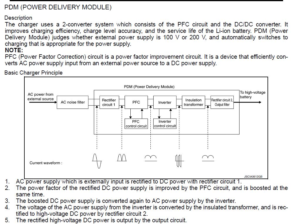
I am not the first one to try this nor I am sure will I be the last to try it. Hoping we can pull all the info into one place and generate some new interest to make this easier for anyone else that wants to give it a try. Thanks ito everyone that has been here a while and thanks in advance for any help with this project. My specific project is to put a Nissan Leaf pack and charger into a 2002 RAV4 EV.
What I know so far.
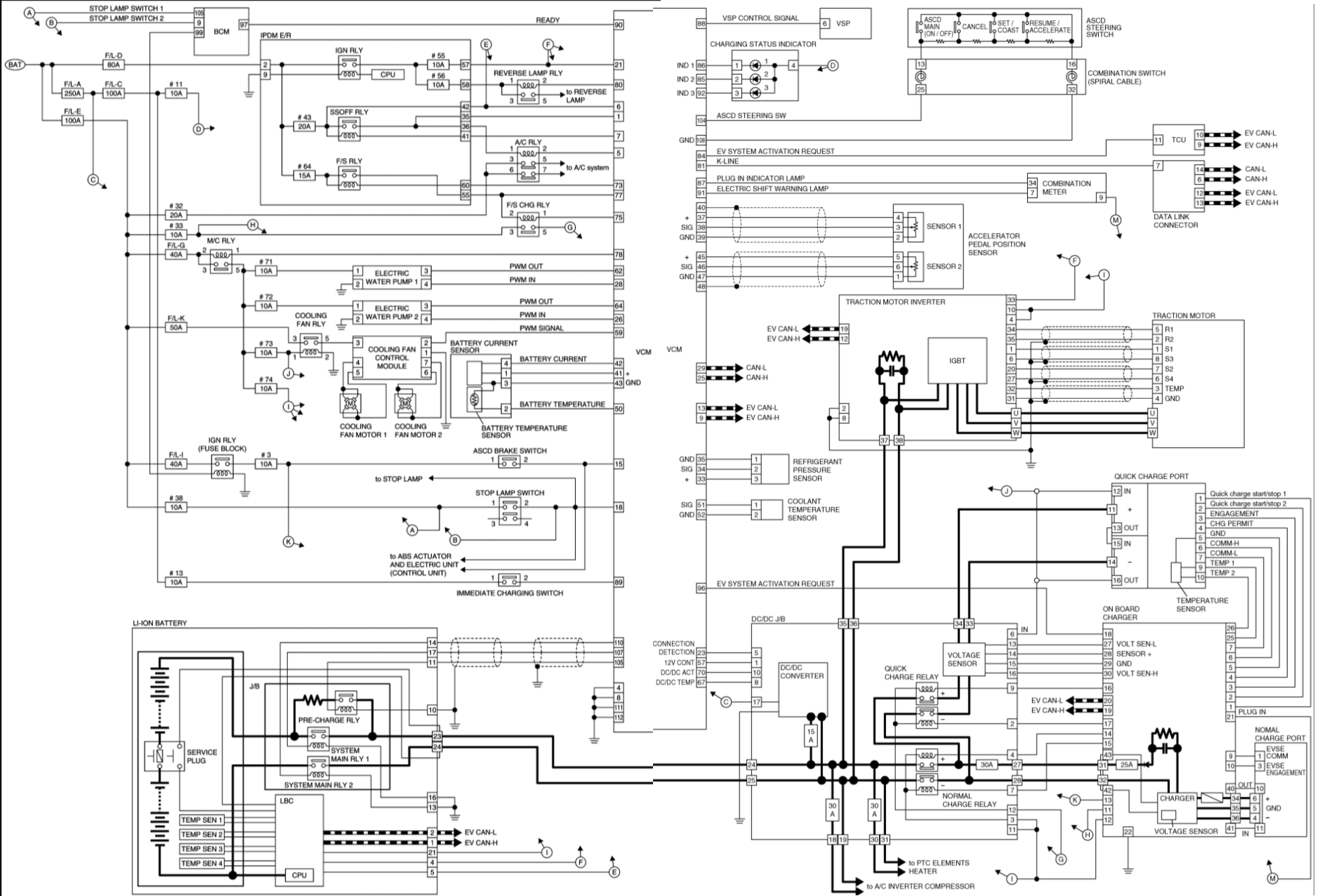
The PDM sits on the "EV SYSTEM CAN Circuit" There are a number of connections on the B24 connector that need to be hard wired in order to function along with an external j1772 charger to start with ChaDemo can come later.
The connections are
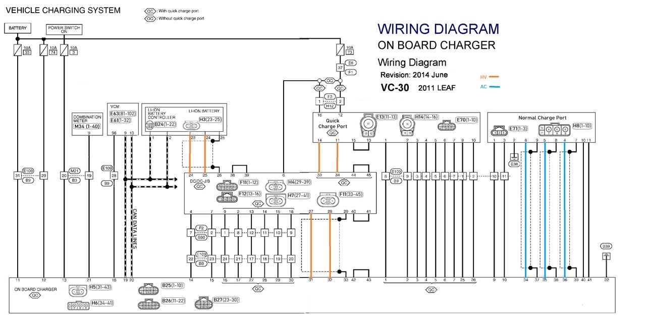
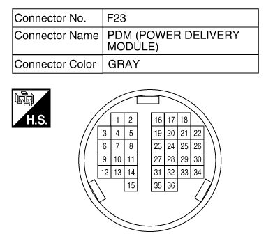
This is the connector :
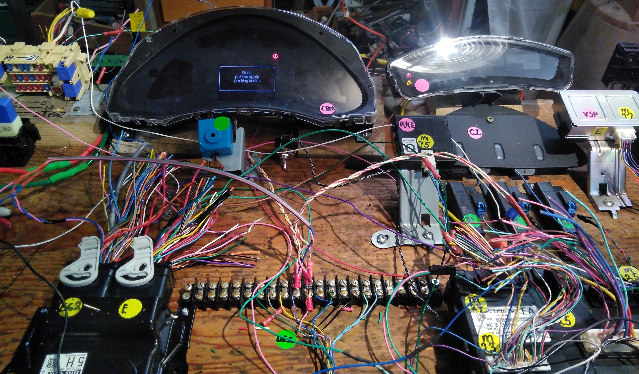
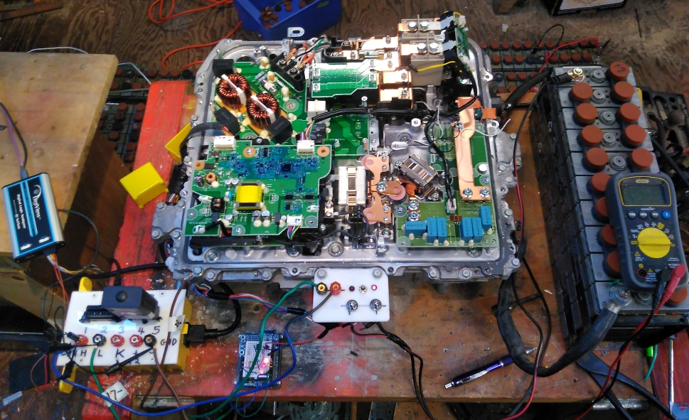
This is my set up :
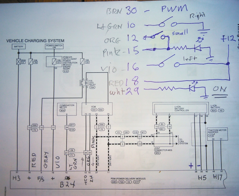
and my connection diagram :
When the PDM powers up all I get is a high on pin 29 and two CAN messages, 0x390 & 0x393 each one transmitted several times
I have a wrecked 2015 and access to complete working 2015 which am going to record can bus charging messages and try and play them back on both the working car and on the stand alone PDM to see what happens. Does anyone know is there a risk of bricking the working car by trying sending messages to the charger. I am also going to pull the VCM, the combination display and the charge lights from the wreck to see if I can cobble that together to assist in the diagnosis of the stand alone PDM. Any and advice appreciated. I am new to can bus so have to learn a lot. I am an electronics tech design and service in the it world with a little OBDII hacking experience.
Peter
Others on this forum have advised the following :
Celeron55 :
Project update: I was unable to reverse the charger CAN protocol to an extent that would have made it do any... well, charging. I did get the DC-DC converter to operate, but that was it.
Basically I found out bit 0x04 in the 0x1f2 frame disables the converter (set low to enable, just spam 0x1f2 00 64 00 a0 00 00 00 00 or so every 10ms). You might also need 50b, 1d4 and maybe 55b (probably not). Anyway, that's worthless without the charging working.
I'm now in the process of developing the necessary hardware mods to get it to charge without any co-operation of Nissan's original software. This is actually going fairly well (I already have full control in a lab setup), but making this reproducible or to be something that I can use daily is more difficult.
EDIT: I've basically reverse-engineered enough of the connections to the Renesas R5F35MEEJFE chip that controls the PDM in order to write a new program from scratch for it to do regular charging and dc-dc conversion. Not sure if I'll do that, I'd need a E8a emulator ($150) and basically IAR Embedded Workbench for M16C ($2000? $4000?) to program it. Also, nobody sells these chips for a hobbyist if the one on board is somehow locked. I can find different ones with the same pinout though, eg. R5F35L2EJFE.
IskeSoderlund:
Hi!
Been lurking here for a while, I'm trying to hack a leaf OBD charger. I've come quite a way closer to charging. I've written a program which makes the charger think it's in the leaf. And it seems to work the charger is no longer sending "fault" signals by CAN. And I'm trying to make it charge by sending the same messages that the VCM sends to the leaf when charging, according to CAN captures by carrot. I still haven't been able to make it charge. Is it possible that the charger like the inverter saves DTC and refuses to start charging? If so what's my best option to remove stored DTCs?
If anyone wants my codes for the program or help with making the charger "think" its in a leaf just contact me!
https://mynissanleaf.com/viewtopic.php?p=620578#p620578I am not the first one to try this nor I am sure will I be the last to try it. Hoping we can pull all the info into one place and generate some new interest to make this easier for anyone else that wants to give it a try. Thanks ito everyone that has been here a while and thanks in advance for any help with this project. My specific project is to put a Nissan Leaf pack and charger into a 2002 RAV4 EV.
What I know so far.
The PDM sits on the "EV SYSTEM CAN Circuit" There are a number of connections on the B24 connector that need to be hard wired in order to function along with an external j1772 charger to start with ChaDemo can come later.
The connections are
- Pin 10, Plug in signal, LightGreen
- Pin 11, EV System CAN-L, DarkGreen
- Pin 12, HV detecting circuit Interlock In, Orange
- Pin 15, HV detecting signal Interlock Out, Pink
- Pin16 Power On (IGN) , Violet
- Pin 18, Battery Power Supply, Red
- Pin 27, EV System CAN-H, Blue
- Pin 29, EVSE Connection Signal, White
- Pin30, EVSE communication PWM, Brown
This is the connector :
This is my set up :
and my connection diagram :
When the PDM powers up all I get is a high on pin 29 and two CAN messages, 0x390 & 0x393 each one transmitted several times
I have a wrecked 2015 and access to complete working 2015 which am going to record can bus charging messages and try and play them back on both the working car and on the stand alone PDM to see what happens. Does anyone know is there a risk of bricking the working car by trying sending messages to the charger. I am also going to pull the VCM, the combination display and the charge lights from the wreck to see if I can cobble that together to assist in the diagnosis of the stand alone PDM. Any and advice appreciated. I am new to can bus so have to learn a lot. I am an electronics tech design and service in the it world with a little OBDII hacking experience.
Peter
Others on this forum have advised the following :
Celeron55 :
Project update: I was unable to reverse the charger CAN protocol to an extent that would have made it do any... well, charging. I did get the DC-DC converter to operate, but that was it.
Basically I found out bit 0x04 in the 0x1f2 frame disables the converter (set low to enable, just spam 0x1f2 00 64 00 a0 00 00 00 00 or so every 10ms). You might also need 50b, 1d4 and maybe 55b (probably not). Anyway, that's worthless without the charging working.
I'm now in the process of developing the necessary hardware mods to get it to charge without any co-operation of Nissan's original software. This is actually going fairly well (I already have full control in a lab setup), but making this reproducible or to be something that I can use daily is more difficult.
EDIT: I've basically reverse-engineered enough of the connections to the Renesas R5F35MEEJFE chip that controls the PDM in order to write a new program from scratch for it to do regular charging and dc-dc conversion. Not sure if I'll do that, I'd need a E8a emulator ($150) and basically IAR Embedded Workbench for M16C ($2000? $4000?) to program it. Also, nobody sells these chips for a hobbyist if the one on board is somehow locked. I can find different ones with the same pinout though, eg. R5F35L2EJFE.
IskeSoderlund:
Hi!
Been lurking here for a while, I'm trying to hack a leaf OBD charger. I've come quite a way closer to charging. I've written a program which makes the charger think it's in the leaf. And it seems to work the charger is no longer sending "fault" signals by CAN. And I'm trying to make it charge by sending the same messages that the VCM sends to the leaf when charging, according to CAN captures by carrot. I still haven't been able to make it charge. Is it possible that the charger like the inverter saves DTC and refuses to start charging? If so what's my best option to remove stored DTCs?
If anyone wants my codes for the program or help with making the charger "think" its in a leaf just contact me!