This one is similar to what Msportronics except that you have to DIY.
http://www.ebay.com/itm/OEM-Nissan-Leaf-VSP-Harness-Mod
Her's what I think happened. Msportronics had to strip 54 wires, then pin crimp 54 microscopic pins. A total of 108 actions each. Lots of time involved. Artist / engineers doing repetitive jobs tend to quit sooner then stop producing. On the brighter side, these are same people that bring us innovations.
For some that want to make your own, here's the part number 25172-3NF0A. Someone sells a generic harness which you have to meticulously plug in up to 9 pins yourself. Probably around 2018 or 2019 is when you can't pay anyone to install it. You're on your own.
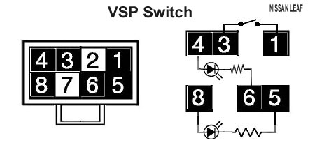
EDIT: Sept 2017: Here's an open source reference diagram, sourced from the service manual. Diagram shows wires going from switch to the VSP sound communication box. And switch Internal diagram. (2011-2017 LEAF). To be used only when at least one front wheel are raised off the ground (for troubleshooting purpose. Don't drive around with the sound off.)
_______________________________________________________________________________
16-pin connector = VSP sound communication box
8-pin connector = switch unit
The upper diagram is for a fixed illumination (which is easier to work with.) The bottom is for adjustable illumination and is a theory only since I haven't yet attempt to connect it. Some might prefer a 50mA fuse but I recommend two 820-Ohm resistors.
The most important wires are 11 to 4 and 11 to 8, ignition battery voltage lead. I'd make sure this wire is a thicker gauge than the rest. 18 gauge is good. Because it' should be strong enough to blow a fuse. This wire must have a secure connection to the VSP unit, Instead, I used two, no less than 820-Ohm resistor right at pin 11. I recommend it. Only problem is the indicator light is about 10% dimmer.
ltbighorn said:
Decimus said:
WIRE SIZES:
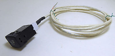
Make sure the lead (wires) are 18 gauge or bigger. Or something that doesn't burn with a 10-Amp load. Small wires can burn, but large wires will pop the fuse. Secondly, the wires have to be wrapped with electrical tape from head to toe, leaving no gaps. The one in the image above is already coated with gray insulation - that's good. This is to help with fire control.
It seems to be like if we're relying on the resistance of the wire to control the current ("large wires will pop the fuse"), that's just asking for trouble/possible fire. The maximum current should be controlled by a resistor, or some other device in the loop, not the wire gauge. Did I miss here as well?
The thicker gauge is to protect the copper wire from burning other stuffs since they're good at popping fuses. Msportronics used tiny wires on his I believe could be unsafe. If they carry 12V, 1-20 Amps then a minimum of 18 gauge is preferred. I believe 18 gauge is common for automotive wires. You probably can use tiny wires if you put the correct resistor at the starting point (on the VSP control unit) exactly what you said at the end.
_____
(WARNING: Do not attempt to connect this unless you are a dealer mechanic. The diagram is for reference only. )