
Ingineer
Well-known member
Does anyone actually know if the Leaf has any method of active balancing in the car? My guess is not.
Most production large-format lithium systems do not have anything except monitoring. I know for sure the PHV (PHEV) Prius does not.
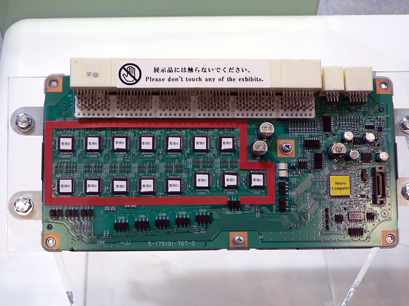
FYI: Here's what inside a Battery ECU on the PHV: (there are 3 of these)
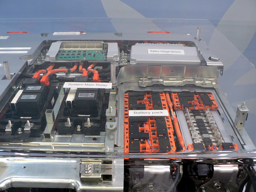
Here's the Pack:
Mod update :
Split from here : http://www.mynissanleaf.com/viewtopic.php?f=27&t=2746&start=0
Most production large-format lithium systems do not have anything except monitoring. I know for sure the PHV (PHEV) Prius does not.
FYI: Here's what inside a Battery ECU on the PHV: (there are 3 of these)
Here's the Pack:
Mod update :
Split from here : http://www.mynissanleaf.com/viewtopic.php?f=27&t=2746&start=0