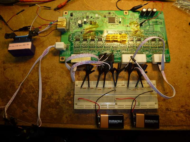
I was fortunate enough to be loaned a BMS board that had been burnt out while trying to converted a Leaf battery pack into a 4 x 100 volt configuration for use in another vehicle.
This is the first time I have looked into a battery controller so some of what I say may be common knowledge. To me it is all new but I though it could be useful to others to know more about the inner working of the battery balancing circuits and how it interfaces with the Leaf.
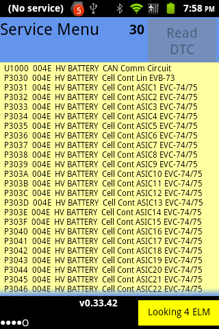
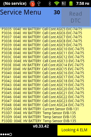
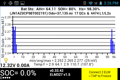
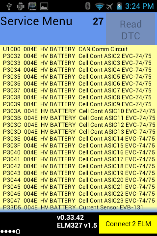
The board consists of two sections. The first section is common to all ECUs in the Leaf with a CAN interface and RISC processor. This is the part that Leaf Spy communicates with to get battery voltages and shunt settings. The second section is almost totally isolated from the first and consists of 24 custom ASICs that monitor the 96 cell pairs. This is the section I have been looking into in detail.
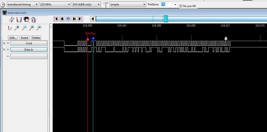
The most interesting part is that the custom ASIC part is coupled to the first section through three photocouplers. Communications with the ASICs is through a serial link starting with a UART pin on the RISC processor and going through the first photocoupler. The output of that photocoupler is looped through the first 12 ASICs then another photocoupler then 12 more ASICs and finally through the last photocoupler back to the RISC processors input UART.
Each ASIC is actually an island onto itself. It gets its power from the four cells it is monitoring and only has a single input signal from its neighbor which with a zener diode is prevent from going negative.
All this isolation is required because the full battery voltage of up to 393 volts is being monitored on a standard circuit board. There is a clear insulating over coating on this section to prevent any leakage that could result in a catastrophic failure of the board.
I am guessing that the zener diodes on the inputs serve two functions. One to dampen any voltage spikes above 6.2 volts. Second to allow the ASIC to function even if one cell is open/shorted. This is important as the command and status must go through all 24 ASICs so they all need to be powered up.
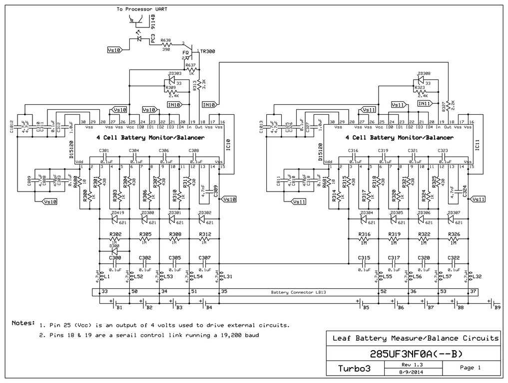
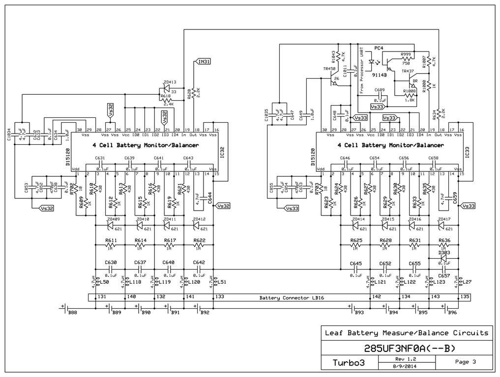
Here is a schematic of the last two ASICs in the chain before the data is shifted back to the processor. Note that the shunt resistor appears to be the 430 ohm 250 mw resistor. So any balancing is going to take a long time at less than a 10 ma load.
Warning: If you are going to try to rewire the BMS to operate with a different battery configuration best to really study this wiring diagram so you understand the voltages your rewiring will put on the ASIC. These are custom chips and as far as I know are only available internally to Nissan or by stripping them off another BMS board.
This shows the last two ASICs in the string before sending data back to the processor through the photocoupler.
The Service Plug that opens the high voltage circuit requires that the BMS also be split into two isolated sections. This page shows the photocoupler used to isolate the serial control signal between the two groups of 12 ASICs. Note that the negative side of cell 48 is not connected to the positive side of cell 49. If this was not done then when the Service Plug was pulled all the power would try to pass through that connection on the BMS board burning it out in a short order.
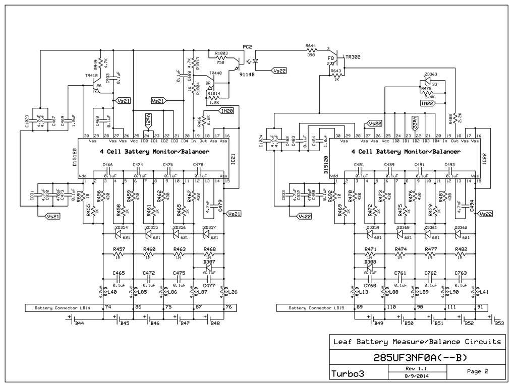
This shows the first two ASICs in the string with the right one getting commands from the processor through the photocoupler.
Not sure of the purpose of TR450. It seems to allow the ASIC to put a load on the ASIC generated Vcc used to power the photocoupler.
This is the first time I have looked into a battery controller so some of what I say may be common knowledge. To me it is all new but I though it could be useful to others to know more about the inner working of the battery balancing circuits and how it interfaces with the Leaf.
The board consists of two sections. The first section is common to all ECUs in the Leaf with a CAN interface and RISC processor. This is the part that Leaf Spy communicates with to get battery voltages and shunt settings. The second section is almost totally isolated from the first and consists of 24 custom ASICs that monitor the 96 cell pairs. This is the section I have been looking into in detail.
The most interesting part is that the custom ASIC part is coupled to the first section through three photocouplers. Communications with the ASICs is through a serial link starting with a UART pin on the RISC processor and going through the first photocoupler. The output of that photocoupler is looped through the first 12 ASICs then another photocoupler then 12 more ASICs and finally through the last photocoupler back to the RISC processors input UART.
Each ASIC is actually an island onto itself. It gets its power from the four cells it is monitoring and only has a single input signal from its neighbor which with a zener diode is prevent from going negative.
All this isolation is required because the full battery voltage of up to 393 volts is being monitored on a standard circuit board. There is a clear insulating over coating on this section to prevent any leakage that could result in a catastrophic failure of the board.
I am guessing that the zener diodes on the inputs serve two functions. One to dampen any voltage spikes above 6.2 volts. Second to allow the ASIC to function even if one cell is open/shorted. This is important as the command and status must go through all 24 ASICs so they all need to be powered up.
Here is a schematic of the last two ASICs in the chain before the data is shifted back to the processor. Note that the shunt resistor appears to be the 430 ohm 250 mw resistor. So any balancing is going to take a long time at less than a 10 ma load.
Warning: If you are going to try to rewire the BMS to operate with a different battery configuration best to really study this wiring diagram so you understand the voltages your rewiring will put on the ASIC. These are custom chips and as far as I know are only available internally to Nissan or by stripping them off another BMS board.
This shows the last two ASICs in the string before sending data back to the processor through the photocoupler.
The Service Plug that opens the high voltage circuit requires that the BMS also be split into two isolated sections. This page shows the photocoupler used to isolate the serial control signal between the two groups of 12 ASICs. Note that the negative side of cell 48 is not connected to the positive side of cell 49. If this was not done then when the Service Plug was pulled all the power would try to pass through that connection on the BMS board burning it out in a short order.
This shows the first two ASICs in the string with the right one getting commands from the processor through the photocoupler.
Not sure of the purpose of TR450. It seems to allow the ASIC to put a load on the ASIC generated Vcc used to power the photocoupler.
")