ripple4
Well-known member
This idea is related to the grid-interactive, but not grid-tied, hybrid inverter that I talked about in this post. (https://www.mynissanleaf.com/viewtopic.php?f=45&t=27295)
I thought this had enough merit or potential other uses to stand on its own and wanted to see if someone had anything to add. The basic idea is to have an EVSE that can sense some amount of current flow, somewhere else, and then increase or decrease car charging dynamically to not exceed some limit. there is a commercial solution for this from some .au address, Zappi, but it's $800. there is also an instrutable for an all-arduino EVSE. What i'm talking about is sort of the best of both worlds, low cost, moderate effort and moderate finish quality.
The issue that I’m wrestling with is how to balance car charging with a off grid inverter without exceeding the power limits of the inverter. The root problem is that if the array/charger/inverter is sized for the car in the winter then there will be an overproduction in the summer, so to use that, it would be great to run an air conditioning unit and house hold loads. However, when I come home in the afternoon I don’t want to have to unplug the AC and click a bunch of transfer switches. Nor do I want to always be limited to 240v/6A when there is full sun and nothing else is running. So the idea I have is to buy a EVSE that is very finely adjustable from 6-16 amps (my 2012 only charges at 16a max) and then put a current transformer on the output of the inverter. Then when the power demand is low for AC and house loads then EVSE will go up to 16a, but when the A/C kicks on or a bunch of loads come on, it will dial it back to 6A. all within the 2 seconds the inverter says it can handle a surge load.
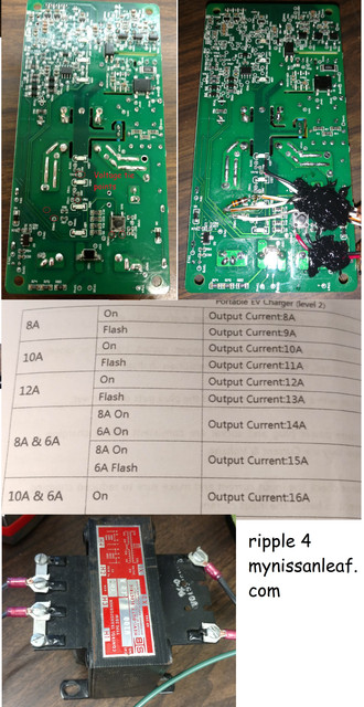
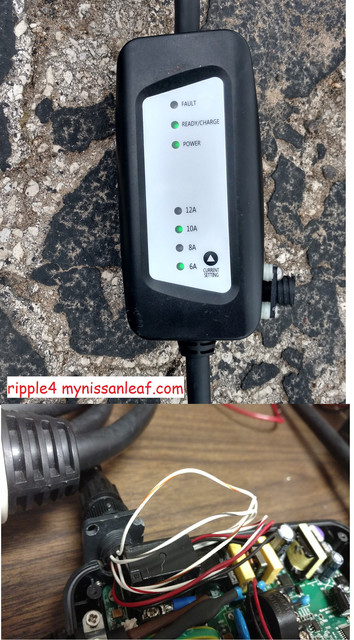
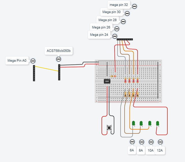
How I think this can be done is buying an inexpensive EVSE replacement brick and sort of hacking it to be microcontroller, well, controlled. The one I’m going to experiment on had LED lights for each current level and a membrade dry contact push button to increase current. So if I tap into the LED signal wires and push button wires into a Arduino, with CNY17F optical isolation and a proper pull down signal conditioning on the digital inputs I will be able to make IF/THEN chain that cycles thought the various current levels and monitor that its at the right one. On the input side of the equation I see myself installing a split core current transfer OR a hall effect current sensor on the output of the inverter and that will measure the current flow going to all the loads added up. I would prefer a turn-key split core CT, unfortunately there is not a 20A signal conditioned CT on eBay that I can find, so the hardest part of all of this for me will be learning to build a CT signal conditioner that the Arduino can read.
I’ve made quite a few Arduino robots around the house, one that turns porch lights on and off with the sunrise/set (https://www.thingiverse.com/make:356106). Ones that runs stepper motors, 8x20 LCDS, SCRs and pneumatic valves, but I always seem to have problems signal conditioning random sensor when it comes to fighting EMI. solenoids and LCD combinations are the worst, i think the LCD is like an antenna right into the CPU. Just to be clear i'm linking to the sources i bought from as a courtesy to interested people, these are not seller links.
$80 adjustable EVSE brick
https://www.aliexpress.com/item/Electric-car-special-charging-controller-circuit-board-of-16A-input110-250V/32790412028.html?spm=a2g0s.9042311.0.0.28734c4dDXr0i8
CT sensor
https://www.ebay.com/itm/YHDC-SCT013-020-Split-Core-Current-Transformer-20A-1V-3-5mm-AC-Current-Sensor/162560986019?ssPageName=STRK%3AMEBIDX%3AIT&_trksid=p2057872.m2749.l2649
Hall sensor
https://www.ebay.com/itm/Current-Sensor-IC-ACS758LCB-050B-100B-PFF-T-Current-Module-US/253320858129?ssPageName=STRK%3AMEBIDX%3AIT&var=552478285260&_trksid=p2057872.m2749.l2649
Zappi comercial current sensing evse
https://www.ebay.com/itm/myenergi-Zappi-7Kw-EVSE-EV-Wall-Charger-LEAF-i3-Tesla/113218017764?hash=item1a5c51d9e4:g:f38AAOSw2Wtbfz85
all arduino EVSE ( not adjustable as presented, but could be with additional PWM code and selector button)
https://www.instructables.com/id/Arduino-EV-J1772-Charging-Station/
I thought this had enough merit or potential other uses to stand on its own and wanted to see if someone had anything to add. The basic idea is to have an EVSE that can sense some amount of current flow, somewhere else, and then increase or decrease car charging dynamically to not exceed some limit. there is a commercial solution for this from some .au address, Zappi, but it's $800. there is also an instrutable for an all-arduino EVSE. What i'm talking about is sort of the best of both worlds, low cost, moderate effort and moderate finish quality.
The issue that I’m wrestling with is how to balance car charging with a off grid inverter without exceeding the power limits of the inverter. The root problem is that if the array/charger/inverter is sized for the car in the winter then there will be an overproduction in the summer, so to use that, it would be great to run an air conditioning unit and house hold loads. However, when I come home in the afternoon I don’t want to have to unplug the AC and click a bunch of transfer switches. Nor do I want to always be limited to 240v/6A when there is full sun and nothing else is running. So the idea I have is to buy a EVSE that is very finely adjustable from 6-16 amps (my 2012 only charges at 16a max) and then put a current transformer on the output of the inverter. Then when the power demand is low for AC and house loads then EVSE will go up to 16a, but when the A/C kicks on or a bunch of loads come on, it will dial it back to 6A. all within the 2 seconds the inverter says it can handle a surge load.
How I think this can be done is buying an inexpensive EVSE replacement brick and sort of hacking it to be microcontroller, well, controlled. The one I’m going to experiment on had LED lights for each current level and a membrade dry contact push button to increase current. So if I tap into the LED signal wires and push button wires into a Arduino, with CNY17F optical isolation and a proper pull down signal conditioning on the digital inputs I will be able to make IF/THEN chain that cycles thought the various current levels and monitor that its at the right one. On the input side of the equation I see myself installing a split core current transfer OR a hall effect current sensor on the output of the inverter and that will measure the current flow going to all the loads added up. I would prefer a turn-key split core CT, unfortunately there is not a 20A signal conditioned CT on eBay that I can find, so the hardest part of all of this for me will be learning to build a CT signal conditioner that the Arduino can read.
I’ve made quite a few Arduino robots around the house, one that turns porch lights on and off with the sunrise/set (https://www.thingiverse.com/make:356106). Ones that runs stepper motors, 8x20 LCDS, SCRs and pneumatic valves, but I always seem to have problems signal conditioning random sensor when it comes to fighting EMI. solenoids and LCD combinations are the worst, i think the LCD is like an antenna right into the CPU. Just to be clear i'm linking to the sources i bought from as a courtesy to interested people, these are not seller links.
$80 adjustable EVSE brick
https://www.aliexpress.com/item/Electric-car-special-charging-controller-circuit-board-of-16A-input110-250V/32790412028.html?spm=a2g0s.9042311.0.0.28734c4dDXr0i8
CT sensor
https://www.ebay.com/itm/YHDC-SCT013-020-Split-Core-Current-Transformer-20A-1V-3-5mm-AC-Current-Sensor/162560986019?ssPageName=STRK%3AMEBIDX%3AIT&_trksid=p2057872.m2749.l2649
Hall sensor
https://www.ebay.com/itm/Current-Sensor-IC-ACS758LCB-050B-100B-PFF-T-Current-Module-US/253320858129?ssPageName=STRK%3AMEBIDX%3AIT&var=552478285260&_trksid=p2057872.m2749.l2649
Zappi comercial current sensing evse
https://www.ebay.com/itm/myenergi-Zappi-7Kw-EVSE-EV-Wall-Charger-LEAF-i3-Tesla/113218017764?hash=item1a5c51d9e4:g:f38AAOSw2Wtbfz85
all arduino EVSE ( not adjustable as presented, but could be with additional PWM code and selector button)
https://www.instructables.com/id/Arduino-EV-J1772-Charging-Station/
")