49thdiver said:Diagram is harness side or H.S.
Ahh, that what HS means next to the drawings in manual.
Dont know that term , thanks

49thdiver said:Diagram is harness side or H.S.

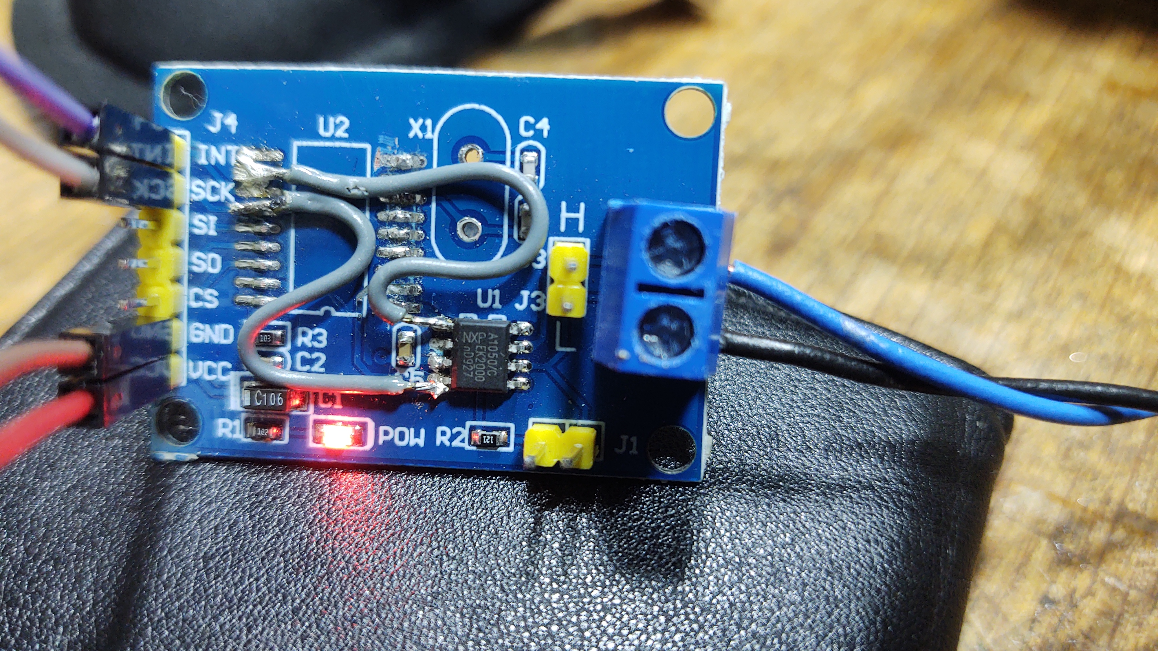
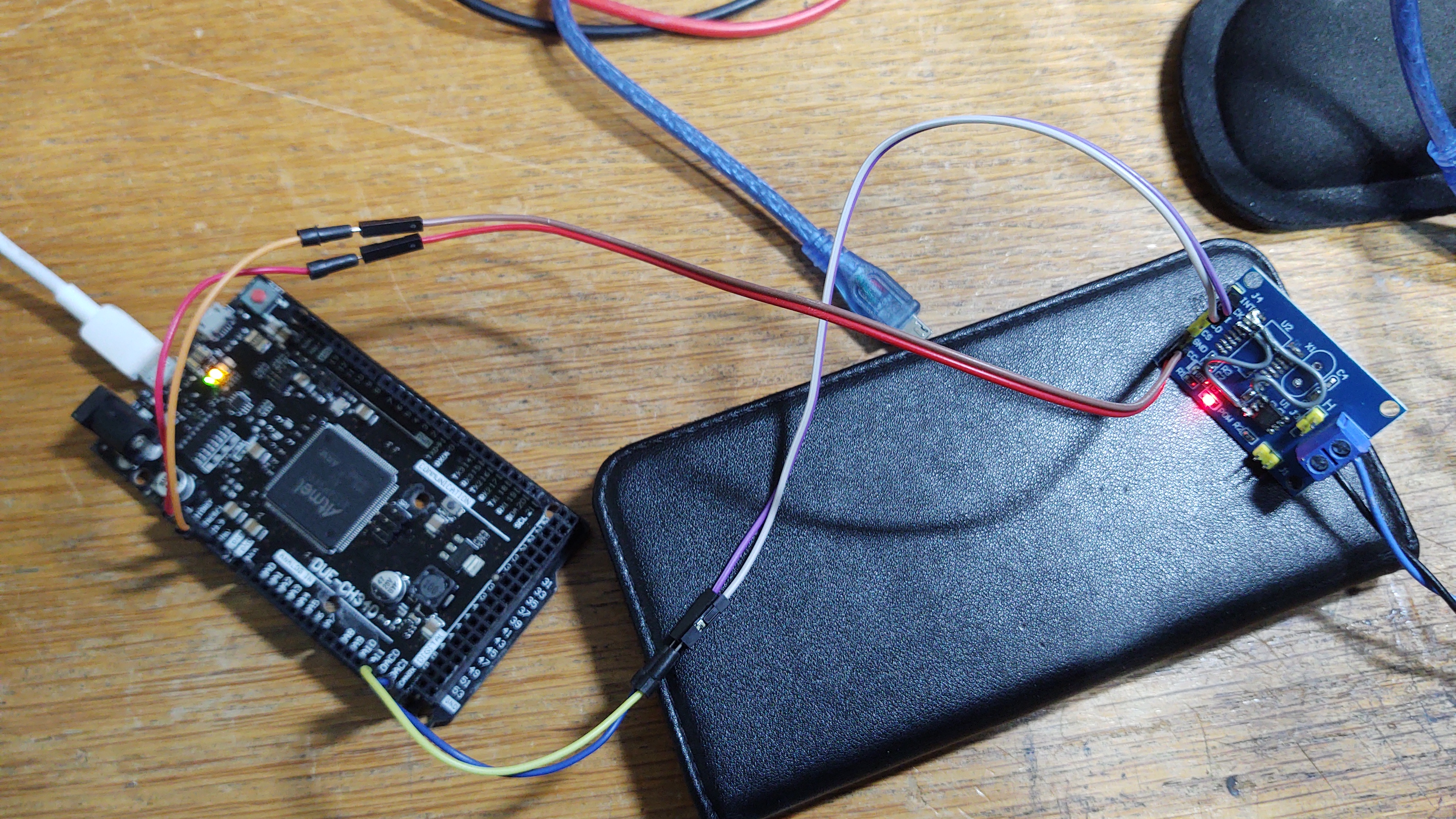
Thanks for getting back.49thdiver said:Yes those little can boards should work, I have some of those but have not had a chance to try them yet.
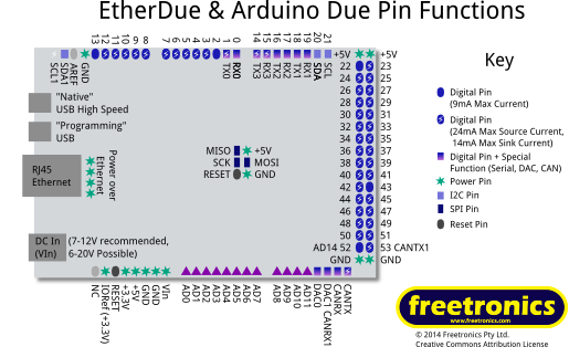
My code is written for the DUE and if you just connect those drivers and it will work with a Gen 2 charger.
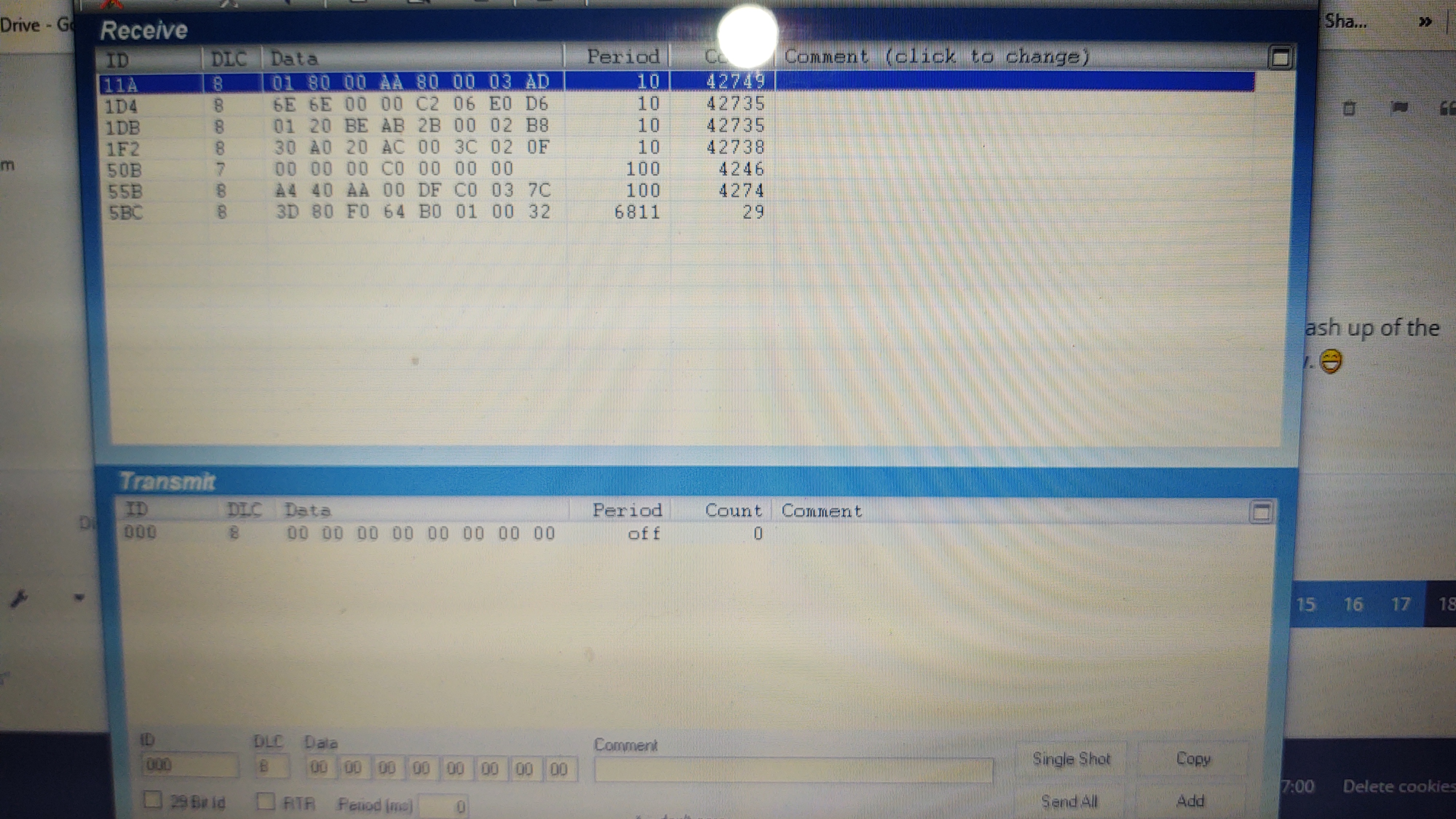
Note if you have an entire gen1 leaf for parts you really only need to connect the VCM and the some of the other control modules and the whole system will work.
I have done this in a Gen 2 complete conversion and it work perfectly with no need for any external controller.
I developed due hardware and software to facilitate using the charger in a factory built 2002 toyota Rav4EV with out any of the other hardware.
Anyway good luck keep me posted.
If I figure out how to I'll post some photos.
Enter your email address to join: