Weekend(s) Project - DIY EVSE

My Nissan Leaf Forum

Help Support My Nissan Leaf Forum:

This site may earn a commission from merchant affiliate links, including eBay, Amazon, and others.

chris1howell

Well-known member
Joined
Aug 10, 2010
Messages
649
Location
Lancaster, Ca
This weekend I decided to see if I could build a control pilot based on the J1772 Spec. I am really frustrated with the current lack of good options. I received an outrageous quote from AV like most others here and I am not about to buy from them and have it installed.

My perfect EVSE would be:
Simple
Small (portable)
Inexpensive
It does not need any features other than those to keep it safe and make it work well. The cars can implement all the cool stuff.

So... I pulled together some parts I had on hand. An Atmel 328 Microcontroller an LCD screen some switches, resistors and a few other basic components.

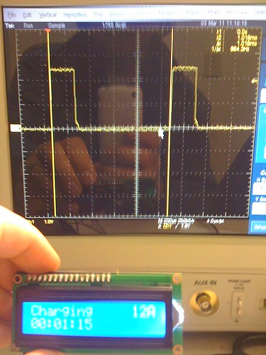
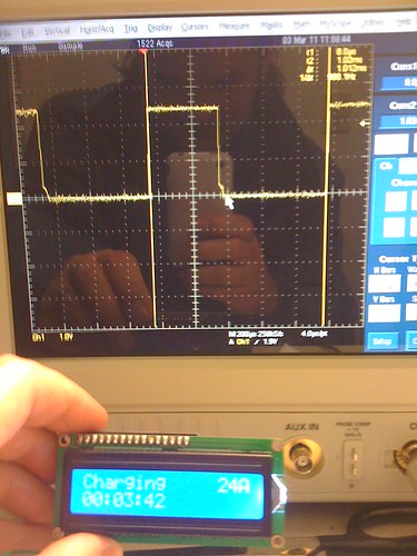
I was able to generate the 1khz pilot signal and use a couple of switches to select higher/lower current settings by telling the micro controller to adjust the duty cycle of the pilot.

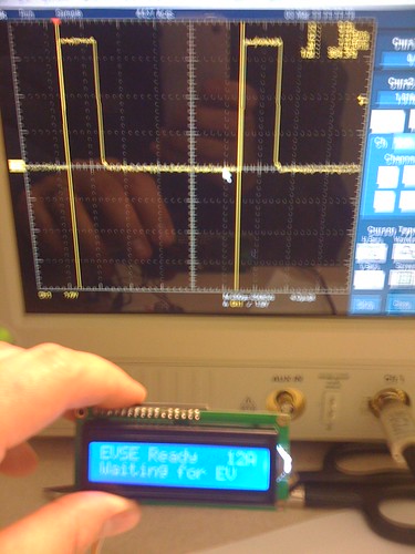
The Micro controller properly detects all the J1772 EV states by “Not Connected" 12V, "EV Connected" 9V, "EV Ready - Charging" 6V - "EV Ready - Ventilation required" 3V and pilot "Error" 0V.

I have not implemented the Negative 12V safety check and GFI detection because I did not have the required parts on hand.

I have posted a pretty bad video on youtube here: http://www.youtube.com/watch?feature=player_profilepage&v=4MfpxmG4zNE
Sorry for the quality, I was late for work but I wanted to get it posted.
 
Good work, Thanks.
No audio with your video?

The little board was your EV-simulator?

What's your next step?
PM if you want any help.

If you put in one external "Reset" input button, then you can control the Max-Current with that. In firmware, detect Reset held for 5 seconds to go into Parm-Set mode. Then, short press to cycle through parms, if there are more than one. For the Max-Current, start low, at perhaps 8 amps, then 12, 16, 24, and 32 amps. Possibly also 10, 15, 20, 30, 40 for 1-hour charging (not a continuous load)?

In any case, nice work.

I found a 40-amp 240v rated relay used for turning A/C systems On/Off. The L1 EVSE appears to use two single-pole relays.

Also, a "Universal" voltage input AC to 12v regulated DC power supply, where one might add some components to make the 5v and -12v? I have not looked extensively for a dual-output unit.

Perhaps add a small relay to switch the power relay, as the L1 EVSE appears to do?

Or, we could take apart an L1 EVSE and actually tell folks what we find, if EVD... does not want to share what they found in the L1 EVSE?
 
Thank you Gary.
Sorry No Audio, I was in a hurry this morning. I will make another video soon. I want to also show a striped down version with no LCD, just LED status indicators and current set by jumpers.

You are correct the little board is my EV simulator.
Both switches off is 2740 Ohms bringing the Pilot from 12V to 9V indicating EV connected.
Switch 1 on brings resistance to 886 Ohms pulling the Pilot to 9V indicating the EV is ready accept to charge
Switch 2 on sets resistance to 246 Ohms and a voltage of 3V indicating Ventilation Required.

I like the 1 button idea. Simple is better, I will make the changes.
I have been looking at components to make this project a full EVSE. My next step is to add the Universal power supply to power the Microcontroller\Pilot\Relay and add the higher power relay control (there is currently an LED in its place). I plan to use a transistor to drive the coil, the ATMEL chip only puts out 40ma. For DC Power I will just use a single output transformer with two regulators to get both 12VDC and 5VDC.
 
With a transformer, you will be making a L2 (or an L1), but not an L1/L2 version, right?

What is generating (will generate) the -12v, nothing yet, right?

Where are you located?
 
Looks awesome! You should chat with David at Modular EV Power as he is currently working on a full EVSE control board.

Any chance we could see some schematics or source code? I don't know much about AVR programming, except I've played around with an Arduino a bunch (it's a special AVR bootloader), but I can't seem to figure out how to output the proper PWM signal from it... Thanks! :D
 
DarkStar: I am willing to share the schematics and source code with select members of this community, I am not ready to make them public. I really do not want to encourage everyone to play with high AC voltages and build their own EVSE's.

What version of the Arduino are you using? The Audrino bootloader has 3 default timers whigh set the PWM Frequency. The newer Arduino's running at 16.000Mhz are running Digital pins 5 and 6 at 16 MHz / 64 / 256 = 976.5625Hz. The information is a bit hard to find but searching for "Arduino PWM" will get you headed in the right direction.
 
chris1howell said:
What version of the Arduino are you using? The Audrino bootloader has 3 default timers whigh set the PWM Frequency. The newer Arduino's running at 16.000Mhz are running Digital pins 5 and 6 at 16 MHz / 64 / 256 = 976.5625Hz which is well within the J1772 Spec. The information is a bit hard to find but searching for "Arduino PWM" will get you headed in the right direction.
Hmm, I I thought the J1772 minimum specification was 980Hz... I've been rockin' the 16MHz Arduino Pro 168 from SparkFun, so maybe I just need to just start trying some things out!
 
Can one set the "256" divider to a slightly lower count?
For best compatibility with cars, a 250 count divider would be a lot closer to 1000 Hz.

GFI:
Sense net current with a current-sensor core/coil. Net current of around + or - 20 ma (maybe 10 to 30 for testing) is probably good.

Display kWh total for the charging session:
Use some (5 or 6?) LEDs to show a count of whole (or half) kWh in binary?

Display Suggestion:
Keep the display port and firmware support for testing and debugging.
 
Gary, make sure that when all that is complete it is UL approved or at least the power circuits are tested to comply to their standards before anyone uses it or builds one for home use. I know you would NEVER use such a device at your home unless it has been tested as such:) After many hours of designing, building, adding cords, enclosure and making it all built to be durable I'm sure it will be very affordable. Not to say it is not a fun experience to do and learn but in the end it will never match a factory EVSE, even a modified unless one spends considerable dollars making it comply to all design standards. If you are so concerned over UL why bother other than to tinker? Since I know how one works I have no reason to build my own although some hobby types may enjoy doing so.

I think if you are going to discuss UL on all the other EVSE products on the forum you may want to discuss them on home-made EVSE projects:)
 
1. Learn and Tinker

2. Perhaps replace the Control Pilot generation function of the micro-processor in the L1/L2 EVSE (already non-UL) of yours?

3. No, not build an entire EVSE, but I support learning.
 
Gary
Yes, you can change the counter to get a perfect 1000hz signal. From my understanding the problem is you lose the ability to set the PWM duty cycle. For tinkering 976.5625Mhz is close enough.
 
garygid said:
1. Learn and Tinker

2. Perhaps replace the Control Pilot generation function of the micro-processor in the L1/L2 EVSE (already non-UL) of yours?

3. No, not build an entire EVSE, but I support learning.


1&3 All good.

2. At this point I would NOT replace that part of the Nissan EVSE as it has not been determined that the unit components can handle the additional amps. Clearly it can be done but I would not at this point but I prefer to error on the safe side when recommending to others. If safety is a concern then the factory built and tested protection circuits are a good bet. Sure, it would be nice to have a few extra amps. I see the L1 modified for 2.8kw to be handy for long trips to friends and other times one needs 2x the 120 speed.
 
:lol: counting kWh, doesn't the car do that?

Maybe that’s a project for next weekend, add voltage and current measurement to get accurate count. My simple EVSE is going to get more complicated...
 
chris1howell said:
:lol: counting kWh, doesn't the car do that?
Car doesn't tell you the kwh used at the plug. People are now using kill a watt or ted for that. Blink will hopefully tell us that ...
 
Gary – Originally, I was planning to use a transformer and rectifier to power the control pilot which, as you point out, would lock the unit to L1 only or L2 only by wiring the coil in series/parallel. However to do it right I am now looking at a switch mode power supply to power the microprocessor with any AC voltage from 90 to 265. I have found a really small switch mode PS that is fully resin encased. The only limitation is it can only supply 3W. Right now I am only using .28 Watts with no LCD and .41 Watts with the LCD. I am worried the Relay coil will eat the remaining ~ 2.5 watts for lunch...
 
I had the opportunity to connect my project to an Oscilloscope today and test the different PWM duty cycles and Voltage outputs. The Pilot signal was measured at 984.3Hz. I tested several duty cycles 12A – 20%, 18A - 30%, and 24A – 40% all looked really good. I also tested all possible states (EV not connected, Connected, Charging and Error) and each state measured as expected. Here are a few pictures…


12A - Charging

12 Amp - Charging by chris1howell, on Flickr

24A - Charging

24 Amp - Charging by chris1howell, on Flickr

12A - EV connected

12A - Connected by chris1howell, on Flickr
 
Back
Top