Extra Battery, How to Integrate with 24kWh Traction Battery?

My Nissan Leaf Forum

Help Support My Nissan Leaf Forum:

This site may earn a commission from merchant affiliate links, including eBay, Amazon, and others.
Yeah, this monday I shot a little segment of video exactly about that. I'm now on the hunt for an SD card reader, which apparently is pure luxury in this neck of the woods because no store seems to carry them.

It fast charges at a - for an old '11 Leaf - blistering rate with the new pack. We were drawing 40kW, of which about 26 was going into the extender and 13ish (the usual rate without extender) was going into the main pack. Interestingly, despite the vast discrepancy, the extender barely warmed up while the main pack heated up to 12 degrees C above ambient. This may also have had to do with us being in the hills and me not really caring about efficiency, so running the car pretty hard.

Long story short: there is literally no reason why anyone with the skills and an old Leaf shouldn't build an extender. It only makes the car better. And the cost or time investment really isn't that huge, at least in Europe. This is $2k in batteries and two weekends of your time.

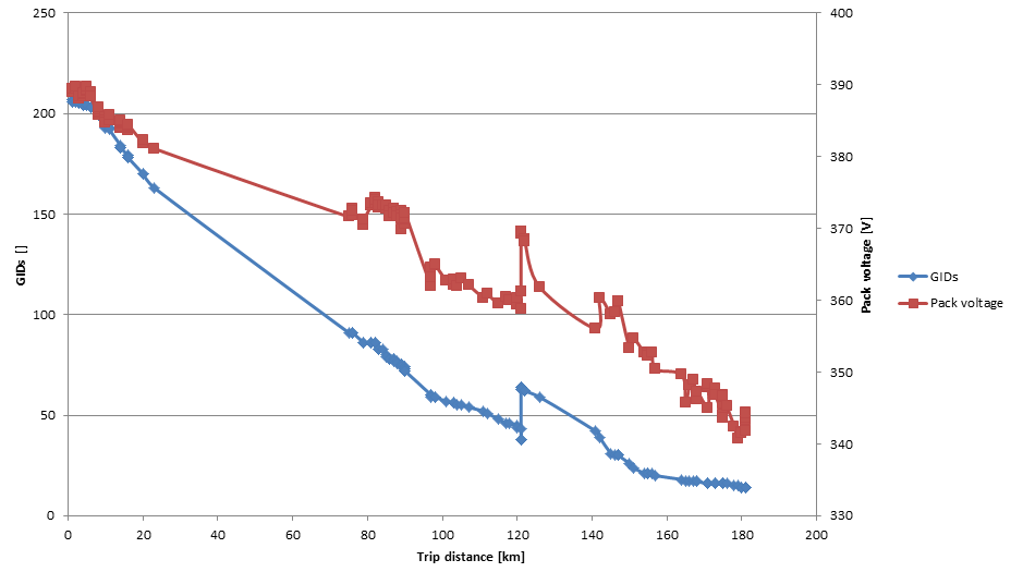
That being said: I'm still holding out to do the full illustrated tutorial until I've cracked the GoM range estimation and centralized BMS readout/balancing. Right now, you have to have balls of steel to use my car; even after VLBW you can comfortably drive another 60-80km on the remaining charge in the extender, but the car will not give you any useful feedback on range. You have to trust Leafspy's voltage.

Today we're going on a little trip to Trier, which is just in range of the car. I'll log it with Leafspy if I find out how that's done.
 
Thanks for the updates MUX!

Here's a question. Have you thought about thermal management? Where I live it gets cold. Really cold. I've seen it hit -40°F (-40°C) just about every year. Or at least stay well below -20°F (-30°C) for several days. That's really the only thing I'm afraid of is killing an extended battery with a poorly designed TMS.

Or make it modular and detachable so I can put it inside when i don't need it?
 
jkenny23 said:
One more question I forgot, have you tried DC fast charging with the nearly double capacity Leaf yet? I recall seeing an earlier experiment when you used a much smaller extender pack, but at that scale it was just along for the ride and wouldn't have made much difference for the total capacity. I'm curious whether the Leaf will give an error when it requests ~50kW from the charger and only sees about half that going into its own battery. Would love to see a LeafSpy charging graph too, whether it allows full charge rate for longer duration since the voltage is rising slower than normal; this is really critical to making the Leaf a true long range car.

When DCQC occurs, the charging unit supplies high voltage DC with a maximum current limit. The BMS of the Leaf then controls the
its own charging current and decreases it over time. When a second battery is added like Mux did, that battery has it own controller for
balancing it cells and "sees" the DCQC just as a voltage source too, i.e. it controls its own charging current. The Leaf's BMS doesn't know
how much current the added battery is using from the DCQC and just controls its own battery's charging current and has no info on the
total current being supplied by the DCQC. This assumes that the second battery is connected directly to the DCQC port of the Leaf
and that both batteries don't consume more current than the set current limit of the DCQC.
 
IssacZachary said:
Thanks for the updates MUX!

Here's a question. Have you thought about thermal management? Where I live it gets cold. Really cold. I've seen it hit -40°F (-40°C) just about every year. Or at least stay well below -20°F (-30°C) for several days. That's really the only thing I'm afraid of is killing an extended battery with a poorly designed TMS.

Or make it modular and detachable so I can put it inside when i don't need it?

If anyone were to copy exactly what I did in such a climate, you would *definitely* need a battery heater, same as in the 2013+ cold weather package and in many ICE cars. It would have to be plugged in continuously to warm the insulated pack with PTC heaters to keep it at whatever temperature the manufacturer rates the pack at to perform nominally. Lithium ion packs have way higher internal resistance and lower allowable charge/discharge currents even at freezing, let alone so far below freezing, probably at altitude too.

It really depends on where you draw the line. Want to keep the battery in tip-top shape? Blanket, PTC heater, pretty high temperatures. Want to just barely scrape by? Probably keep it insulated or in a garage at more than the rated minimum temperature (which is -25C in this case).

------------------------

In other news, I tried to log my trip to Trier and back. Unfortunately, Leafspy keeps disconnecting every so often, so there are some gaps in the data:

full.png


This data was procured by filtering the CAN log whenever the motor was idle (<2A current draw/supply). The jump in the graph was a 1h slow-charging session when we were parked for groceries.

The data isn't quite smooth yet, but it shows very clearly that the pack 'normally' discharges at the start, and then flattens out a lot towards the end. Whenever I can get a full log of a charging session, I think we'll be able to properly see the voltage characteristic. Problem there is that I need to somehow keep leafspy connected for ~10 hours.
 
lorenfb said:
The Leaf's BMS doesn't know
how much current the added battery is using from the DCQC and just controls its own battery's charging current and has no info on the
total current being supplied by the DCQC. This assumes that the second battery is connected directly to the DCQC port of the Leaf
and that both batteries don't consume more current than the set current limit of the DCQC.
I'm pretty sure that the way the Chademo protocol works is that the battery controller on the Leaf has to tell the charging station how much current to provide. I don't believe there is any electrical mechanism within the leaf to throttle the current going to the Leaf battery, the Leaf depends on the Chademo station to control the charging current at its direction.

Cheers, Wayne
 
Based on the charging characteristic of Li-Ion I would be very surprised if there is only a voltage control in the protocol. The first part of the charging curve is constant current (max ~120A in my experience watching Leaf Spy) then quickly drops current off in constant voltage mode at ~4.1V/cell.
 
wwhitney said:
lorenfb said:
The Leaf's BMS doesn't know
how much current the added battery is using from the DCQC and just controls its own battery's charging current and has no info on the
total current being supplied by the DCQC. This assumes that the second battery is connected directly to the DCQC port of the Leaf
and that both batteries don't consume more current than the set current limit of the DCQC.
I'm pretty sure that the way the Chademo protocol works is that the battery controller on the Leaf has to tell the charging station how much current to provide. I don't believe there is any electrical mechanism within the leaf to throttle the current going to the Leaf battery, the Leaf depends on the Chademo station to control the charging current at its direction.

Cheers, Wayne

So you're implying that a DCQC device is a current source versus a voltage source? If that's true, how would the current be divided between
Mux's add-on battery and the Leaf's actual battery which is controlled by the Leaf's BMS? And how would the add-on battery ever become
fully charged, e.g. the required current is unknown?
 
jkenny23 said:
Based on the charging characteristic of Li-Ion I would be very surprised if there is only a voltage control in the protocol. The first part of the charging curve is constant current (max ~120A in my experience watching Leaf Spy) then quickly drops current off in constant voltage mode at ~4.1V/cell.

Correct. The Leaf's BMS "sees" the DCQC's voltage and uses it (modulates it if you will) to develop a charging current which it lowers over time
as the battery achieves full charge. The same process occurs when using L1/L2 charging with the exception of not having to convert the AC
to DC.
 
lorenfb said:
So you're implying that a DCQC device is a current source versus a voltage source?
I guess that is the implication. I certainly believe that the only parts in the Leaf that participate in a Chademo charge session are the BMS computer and the battery itself, I don't believe there are any power electronics on the Leaf involved.

lorenfb said:
If that's true, how would the current be divided between
Mux's add-on battery and the Leaf's actual battery which is controlled by the Leaf's BMS? And how would the add-on battery ever become
fully charged, e.g. the required current is unknown?
Well, I haven't been following the details of this thread, but I presume the new pack is installed in parallel with the existing pack. In which case they would necessarily be at the same voltage at all times. The current from the Chademo station would divide between the packs according to their resistances. That would presumably be related to pack size: e.g. if during charging the add-on pack climbs the voltage curve twice as fast (for a given charging current) as the original pack (if the add-on pack had half the capacity), then the requirement that the two packs maintain the same voltage would imply that 1/3 of the current would go to the add-on pack, and 2/3 of the current would go to the original pack.

Cheers, Wayne
 
Isn't controlling the voltage the same as controlling the current? If the DCQC outputs a voltage above the battery pack's, a charging current flows. To control the charge rate, the BMS would request a particular voltage. With the add-on pack there, the DCQC has to supply more current maintain the voltage. The part I'm curious about is what happens if the BMS requests a voltage that exceeds the DCQCs current capacity because it doesn't know about the second pack. Hopefully, the DCQC would just modulate the voltage to output it's maximum current. However, it could decide it was an error for the BMS to request a voltage that exceeds the charger's capacity.
 
davewill said:
Isn't controlling the voltage the same as controlling the current? If the DCQC outputs a voltage above the battery pack's, a charging current flows. To control the charge rate, the BMS would request a particular voltage. With the add-on pack there, the DCQC has to supply more current maintain the voltage. The part I'm curious about is what happens if the BMS requests a voltage that exceeds the DCQCs current capacity because it doesn't know about the second pack. Hopefully, the DCQC would just modulate the voltage to output it's maximum current. However, it could decide it was an error for the BMS to request a voltage that exceeds the charger's capacity.
The question is where the current and voltage are being measured and where they are being regulated.

Current coming into the main bus splits into everything connected to the main bus. This not only includes the traction battery, but also accessories if the car is turned on. For an example, I've ran the A/C while charging from CHAdeMO once. The same must be true for any auxiliary range extending battery.

From what i understand the Leaf asks for current. I would guess it ramps up current until it reaches a voltage threshold, at which point it maintains that current until the voltage changes. At the same time the CHAdeMO station is communicating back to the car the amount of current it is sending. Basically the car asks and the station gives that much or less. If the car asks for 30 amps but the station can only put out 20 for whatever reason the station replies back "I'm sending you 20" and sends just that.
 
wwhitney said:
lorenfb said:
So you're implying that a DCQC device is a current source versus a voltage source?
I guess that is the implication. I certainly believe that the only parts in the Leaf that participate in a Chademo charge session are the BMS computer and the battery itself, I don't believe there are any power electronics on the Leaf involved.

lorenfb said:
If that's true, how would the current be divided between
Mux's add-on battery and the Leaf's actual battery which is controlled by the Leaf's BMS? And how would the add-on battery ever become
fully charged, e.g. the required current is unknown?
Well, I haven't been following the details of this thread, but I presume the new pack is installed in parallel with the existing pack. In which case they would necessarily be at the same voltage at all times. The current from the Chademo station would divide between the packs according to their resistances. That would presumably be related to pack size: e.g. if during charging the add-on pack climbs the voltage curve twice as fast (for a given charging current) as the original pack (if the add-on pack had half the capacity), then the requirement that the two packs maintain the same voltage would imply that 1/3 of the current would go to the add-on pack, and 2/3 of the current would go to the original pack.

Cheers, Wayne

1. Yes, his pack is in parallel and at the same voltage.

2. If the input is really a current source and current divides, how would one ever be assured that the add-on battery was fully charged
when the Leaf's BMS reduced the charging current to a very low value. Since the Leaf's battery is larger, its series resistance would
be lower (an assumption) resulting in a lower charging voltage for the second battery, thereby potentially resulting in an incomplete
charge for the add-on once the Leaf's BMS stopped the charging or reduced it to a very low level. Furthermore, if the Leaf's BMS
found that the charging current was less or greater than desired at any point in time, it would change the current affecting the add-on.

3. We are both attempting to determine how the DCQC might function with two batteries connected in parallel and where one battery is controlling the total charging current. Unless you can document that the DCQC is a current source, the charging method whether using
L1/L2 or DCQC is the same - using a voltage source input and pulse width modulating the input voltage to achieve a desired charging current.
Obviously the DCQC device becomes much more costly for the electric company providing the charging station and they're no longer providing a simple service as usual which is just supplying a simple voltage to its users.
 
IssacZachary said:
davewill said:
Isn't controlling the voltage the same as controlling the current? If the DCQC outputs a voltage above the battery pack's, a charging current flows. To control the charge rate, the BMS would request a particular voltage.

Or use the DCQC's standard output voltage (~400V) and pulse it (switch it on/off in the BMS or possibly in the DCQC itself) to achieve the
desired average charging current just as it does when a L1/L2 charging occurs, since the BMS is constantly measuring the charging
current. That's the most efficient method from an energy transfer process.
 
lorenfb said:
2. If the input is really a current source and current divides, how would one ever be assured that the add-on battery was fully charged
when the Leaf's BMS reduced the charging current to a very low value.
If the chemistry is the same as the original pack (which I assume), then the way the voltage reflects state of charge should be the same for both packs. So if the BMS throttles charging current using a voltage-based estimate of the state of charge of the packs, the add-on pack should be at the same state of charge as the main pack.

Look at it this way: the Leaf BMS is going to run the packs in a operating range from some V_max down to some V_min. Whatever capacity the add-on pack has between V_max and V_min is the extra capacity you are going to get from the add-on pack. If due to different thermal environments or for some other reason the add-on pack would optimally be charged to V_max + 10 mV, then that small portion of the potential capacity of the add-on pack will not be realized.

Cheers, Wayne
 
There's several threads about it in detail, here's a video with some more detail, in the beginning he mentions the car asking for a certain current which was more than the charger can output so it delivered the max it could instead (25kW): https://youtu.be/ddKkffUKZWE
 
wwhitney said:
lorenfb said:
2. If the input is really a current source and current divides, how would one ever be assured that the add-on battery was fully charged
when the Leaf's BMS reduced the charging current to a very low value.

wwhitney said:
If the chemistry is the same as the original pack (which I assume), then the way the voltage reflects state of charge should be the same for both packs. So if the BMS throttles charging current using a voltage-based estimate of the state of charge of the packs, the add-on pack should be at the same state of charge as the main pack.

Assuming that the chemistry is the same is not realistic. Read how Mux sourced the add-on battery.

wwhitney said:
Look at it this way: the Leaf BMS is going to run the packs in a operating range from some V_max down to some V_min. Whatever capacity the add-on pack has between V_max and V_min is the extra capacity you are going to get from the add-on pack. If due to different thermal environments or for some other reason the add-on pack would optimally be charged to V_max + 10 mV, then that small portion of the potential capacity of the add-on pack will not be realized.

Cheers, Wayne

I totally agree! Let's get back to determining how the DCQC device functions when connected to the Leaf. Then we can discuss the details
of how the add-on battery gets fully charged during a standard Leaf QC. I may be wrong, as I always assumed a "dumb" DCQC that only
supplied a fixed and constant voltage with fold-back current limiting as the power output of the DCQC exceeded a certain level.
 
I believe I posted this earlier but since the discussion has come up again, I did a small scale experiment a while back charging/discharging 2 parallel different capacity/chemistry cells and found the current sharing depends mostly internal resistance and capacity, but shifts depending on the discharge curve as mux has found: https://secondlifestorage.com/t-Different-Size-Parallel-Cell-Experiment?pid=25652#pid25652
 
lorenfb said:
Assuming that the chemistry is the same is not realistic. Read how Mux sourced the add-on battery.
OK, as I said I haven't been following. If the V_min / V_max of the add_on pack doesn't match the original pack, that's problematic. If the new pack has a range that is strictly bigger on both sides, then the only effect is that the add on pack is used at less than its full capacity. If the new pack has a higher V_min or a lower V_max, then the Leaf BMS may end up damaging the add on pack if you exceed those limits during your use of the combined pack.

lorenfb said:
I may be wrong, as I always assumed a "dumb" DCQC that only
supplied a fixed and constant voltage with fold-back current limiting as the power output of the DCQC exceeded a certain level.
As I and others have said, that is not how DCQC works. All of the power electronics are in the DCQC station; fundamentally all the onboard BMS does is ask for a particular current level. There may also be communication about maximum and minimum allowable voltages, I don't know.

Cheers, Wayne
 
lorenfb said:
I totally agree! Let's get back to determining how the DCQC device functions when connected to the Leaf. Then we can discuss the details
of how the add-on battery gets fully charged during a standard Leaf QC. I may be wrong, as I always assumed a "dumb" DCQC that only
supplied a fixed and constant voltage with fold-back current limiting as the power output of the DCQC exceeded a certain level.

Additionally since the Leaf's BMS already has the current monitoring function, as do all BEVs' BMSs, it's superfluous to also have
the DCQC do that function, i.e. more costly for the DCQC device than just having the Leaf's BMS switch the DC voltage (~ 400V) on/off
from the DCQC via communications versus actually encoding & sending an actual charging current value. The battery will integrate
that on/off voltage from the DCQC, resulting in the desired charging current. That would result in a simpler and more reliable system.
From the Leaf's charging function, it would be basically the same as when charging via L1/L2.

It would be valuable if there were a spec sheet on a DCFC device that would explicitly define its functions. Maybe someone can link to one.
 
lorenfb said:
Additionally since the Leaf's BMS already has the current monitoring function, as do all BEVs' BMSs, it's superfluous to also have
the DCQC do that function, i.e. more costly for the DCQC device than just having the Leaf's BMS switch the DC voltage (~ 400V) on/off
from the DCQC via communications versus actually encoding & sending an actual charging current value. The battery will integrate
that on/off voltage from the DCQC, resulting in the desired charging current. That would result in a simpler and more reliable system.
From the Leaf's charging function, it would be basically the same as when charging via L1/L2.

It would be valuable if there were a spec sheet on a DCFC device that would explicitly define its functions. Maybe someone can link to one.

That is an overly simplistic description of a switching power supply, and would not be practical to have "feedback" via the Leaf and the relatively low speed CAN bus that CHAdeMO uses. The DC fast charger is a very large switching power supply, which takes in (typically I believe) 3 phase AC, rectifies it to high voltage DC, then steps it down to DC near the battery voltage, and feeds it at constant current to the car's battery which is directly connected through another set of contactors. From what I gathered in the video I linked earlier, the car (BMS) requests a charging current, and the DCQC feeds that current (or a lower amount if it cannot deliver as much as was requested), and also tells the car what voltage it is outputting. The car then modifies this current request as needed to make sure the battery is in the safe operating area (limited by temp, current, voltage).

There used to be a pdf from the CHAdeMO association that described this all, but it has since been removed/restricted, and I can't find any mirrors.

Edit: Found it at the web archive: https://web.archive.org/web/20151223161337/chademo.com/pdf/interface.pdf Good read and overview of how the CHAdeMO system works.
 
Back
Top