
EDIT: This one is sold but I have recieved alot of inquires about custom builds. YES I definitely take orders for anything you would like to see in your EVSE. Lead time is only 3 days. Private message me or if you have a general question you think the rest of the community can benefit from post it here.
60A 14.4kW Premium OpenEVSE L2 with built in current display & RGB LCD display w/Real Time Clock, v3 Main Board
I bought a 2013 Nissan LEAF and love it! I have a heavy electrical background and was inspired when i saw some DIY units for sale here. Work has been very slow and my employer is still weeks behind in paying the other employee and I. This has caused a severe financial hardship. It's a very stressfull time with 2 little boys. I need to support my family anyway I can and am hoping to build and sell a few EVSE's. Thanks for reading this, Now on to the fun stuff!!
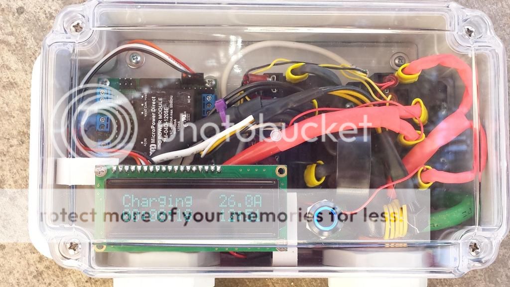
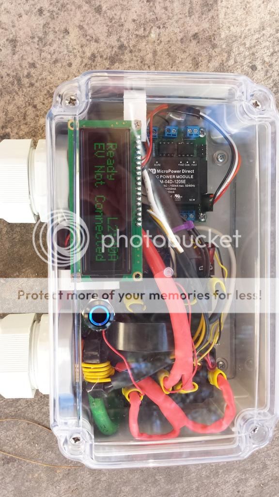
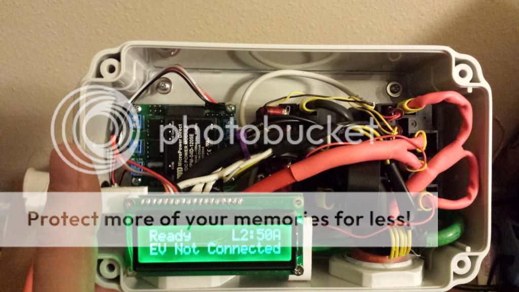
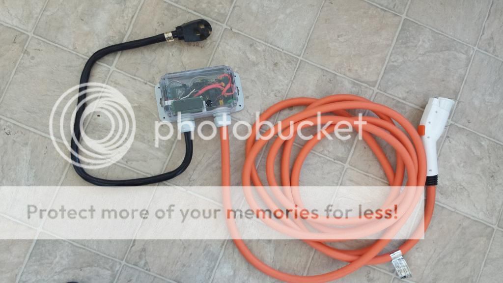
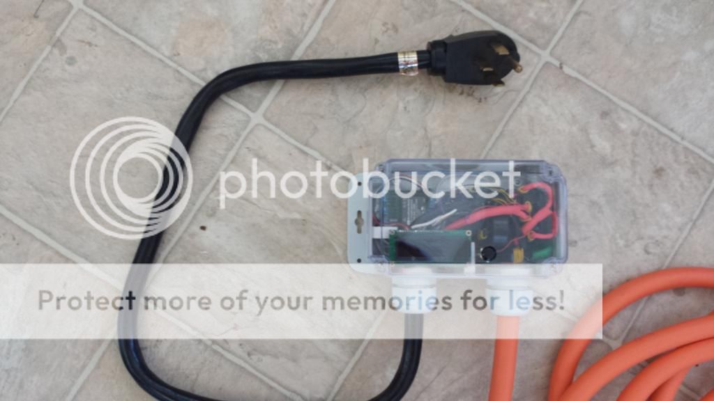
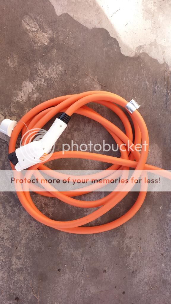
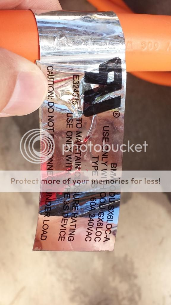
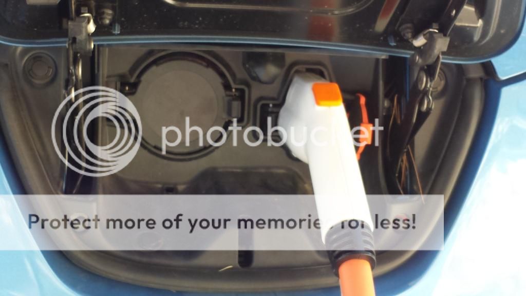
I have a Premium High Power OpenEVSE for sale I built this one to be the best of the best! its running Chris's latest and greatest version 3 main board now with built in current reading right on the LCD! I used his best LCD the RGB model that changes colors for diferent status and Real Time Clock that allows you to set a delay timer great for those of us that can sign up with discounted night time electic rates. I went with a SHEILDED BMW 60A J1772 23 foot cable. It has a Dolstar 70A plug. This unit operates at 240VAC. This is mounted in a very nice PolyCase WC Series Polycarbonate Enclosure with Clear Cover - NEMA Rated for outdoor use. This unit requires a common NEMA 14-50 outlet for 50A use or can be hard wired for 60A. The cost is $521 plus $25 for UPS ground shipping in the continential USA. the premium board/LCD/2nd ct xformer and heavy J1772 Whip really add alot to the cost as you can see but make the best unit you can own!
It will charge any J1772 compliant car at up to 50A (60A Hardwired)
The EVSE current (amps) may be set in multiple steps
Memory is retained automatically.
I can now customize the firmware to whatever values you like before shipping. I chose these values to give the user flexability for various outlets found in the wild. I stop at 60A as this is what the relays and cables are rated for. This unit is constructed with 60A components except for the 14-50 plug itself. It is designed to plug into a 14-50 outlet. 48A is 80% of 60A and it is the maximum allowed for a continuous load when hardwired. I go higher on the 120v side than you normally get so if you use a RV 30A outlet you can take advantage of faster charging. in my test my LEAF could pull 2.64kilowatts (22A @ 120V)
Case Specs:
Case measures 7.63 x 4.63 x 3.09 in.
Designed to IP65 of IEC 529 and NEMA 1, 2, 4, 4x, 12 and 13 specifications
Silicone rubber gasket makes this ideal for outdoor use in a wide range of adverse conditions
Molded on surface-mounting flanges
Captive, stainless steel screws thread into brass inserts for cover on/cover off applications
UL Listed to UL508-4x specifications (File E194432)
Main Board Specs:
Open Source - Hardware (Creative Commons 3.0 BY-SA) and Firmware (GNU GPL v3)
Fully supports SAE J1772 Recommended Practice
Software adjustable pilot (8A – 80A)
4W Switch Mode Power Supply Integrated
Built in GFCI with 20ma trip point
Supports all J1772 states including “ventilation required”
Supports Diode check
Ground verification and Stuck Relay detection
Specs:
OpenEVSE v.3 board running the latest firmware
All nults/bolts/washers are STAINLESS STEEL
The base plate inside is 1/4" thick high quality plex ,no thin stuff here.
The QUAD relay bank is Potter & Brummfiled 60A per Phase
The input cable is 5ft. with the popular NEMA 14-50 plug. This is the one all the Tesla guys have installed as well as the standard at RV parks!
you can even use the plugshare app and set the filters to include NEMA 14-50 and see all of them in the country, there are a suprising number of them.
It has a monochrome black on yellow display
23ft. 60A heavy duty SHEILDED J1772 cable with a Dostar 70A plug
I used a black metal blue lighted ring Menu/Select button. with IP65 water resistance rating
Heat shrink tubing used through out.
All parts are new.
Works with the following vehicles and more!
Nissan LEAF
Toyota RAV4
Toyota Prius Plugin
Chevrolet Volt
Chevrolet Spark EV
Mitsubishi i-MiEV
BMW i3
BMW i8
Cadillac ELR
Fiat 500e
Ford C-Max Energi
Ford Fusion Energi
Ford Focus Electric
Honda Accord Plug-in Hybrid
Smart ForTwo Electric Drive
Porsche Panamera S E-hybrid
Toyota Prius Plug-in Hybrid
Volkswagen E-Golf
Kia Soul EV
Tesla Model S (with included OEM J1772 adapter)
Tesla Model X (with included OEM J1772 adapter)
It will charge any J1772 compliant car at up to 60A including home built/converted cars with a J1772 inlet installed.
here is a link to the owners manual:
https://code.google.com/p/open-evse/wiki/Users_Guide
Here is a video on me demo'ing the unit:
http://youtu.be/wCW8v51NccE" onclick="window.open(this.href);return false;
If you would like the unit customized with a twist lock plug for example or something other than the Nema 14-50 plug I can do that for the difference in parts.
I take custom orders for personalized builds, just shoot me a private message or post here and I will be happy to quote you a great price.
If you would like to see it in action on your EV we can arrange that thru private message at my home. Local pickup in Las Vegas near Smith's grocery on E Flamingo or near The Strip is available. Payment is by Paypal if shipped or cash for local pickup.
Please post any comments or questions here or PM me if you like. Slide show of pics:
http://s762.photobucket.com/user/civic09/slideshow/60A%20Home%20EVSE" onclick="window.open(this.href);return false;
The pics:
LEGAL DISCLAIMER: Because of lawyers I have to add this. This EVSE is intended for use ONLY by responsible adults. Because they are hand-made, they are not UL listed - but are made from UL listed parts. 240v electricity is serious business and caution should be exercised while using any EVSE. For safety's sake, do not use this EVSE outdoors in inclement weather unless it is a model that specifically says Outdoor or Waterproof. You should always install a GFCI breaker not a standard one for any and all circuits a person can come in contact with This EVSE has a GFCI built inside that protects from that point down line. (The J plug side of the the EVSE is safe for outdoors in all weather). BY PLACING AN ORDER WITH US, YOU ASSUME ALL RISK ASSOCIATED WITH USING THIS EVSE AND AGREE THAT WE ARE NOT LIABLE FOR ANY DAMAGE THAT MAY RESULT FROM THEIR USE.
60A 14.4kW Premium OpenEVSE L2 with built in current display & RGB LCD display w/Real Time Clock, v3 Main Board
I bought a 2013 Nissan LEAF and love it! I have a heavy electrical background and was inspired when i saw some DIY units for sale here. Work has been very slow and my employer is still weeks behind in paying the other employee and I.
This has caused a severe financial hardship. It's a very stressfull time with 2 little boys. I need to support my family anyway I can and am hoping to build and sell a few EVSE's. Thanks for reading this, Now on to the fun stuff!!I have a Premium High Power OpenEVSE for sale I built this one to be the best of the best! its running Chris's latest and greatest version 3 main board now with built in current reading right on the LCD! I used his best LCD the RGB model that changes colors for diferent status and Real Time Clock that allows you to set a delay timer great for those of us that can sign up with discounted night time electic rates. I went with a SHEILDED BMW 60A J1772 23 foot cable. It has a Dolstar 70A plug. This unit operates at 240VAC. This is mounted in a very nice PolyCase WC Series Polycarbonate Enclosure with Clear Cover - NEMA Rated for outdoor use. This unit requires a common NEMA 14-50 outlet for 50A use or can be hard wired for 60A. The cost is $521 plus $25 for UPS ground shipping in the continential USA. the premium board/LCD/2nd ct xformer and heavy J1772 Whip really add alot to the cost as you can see but make the best unit you can own!
It will charge any J1772 compliant car at up to 50A (60A Hardwired)
The EVSE current (amps) may be set in multiple steps
Memory is retained automatically.
I can now customize the firmware to whatever values you like before shipping. I chose these values to give the user flexability for various outlets found in the wild. I stop at 60A as this is what the relays and cables are rated for. This unit is constructed with 60A components except for the 14-50 plug itself. It is designed to plug into a 14-50 outlet. 48A is 80% of 60A and it is the maximum allowed for a continuous load when hardwired. I go higher on the 120v side than you normally get so if you use a RV 30A outlet you can take advantage of faster charging. in my test my LEAF could pull 2.64kilowatts (22A @ 120V)
Case Specs:
Case measures 7.63 x 4.63 x 3.09 in.
Designed to IP65 of IEC 529 and NEMA 1, 2, 4, 4x, 12 and 13 specifications
Silicone rubber gasket makes this ideal for outdoor use in a wide range of adverse conditions
Molded on surface-mounting flanges
Captive, stainless steel screws thread into brass inserts for cover on/cover off applications
UL Listed to UL508-4x specifications (File E194432)
Main Board Specs:
Open Source - Hardware (Creative Commons 3.0 BY-SA) and Firmware (GNU GPL v3)
Fully supports SAE J1772 Recommended Practice
Software adjustable pilot (8A – 80A)
4W Switch Mode Power Supply Integrated
Built in GFCI with 20ma trip point
Supports all J1772 states including “ventilation required”
Supports Diode check
Ground verification and Stuck Relay detection
Specs:
OpenEVSE v.3 board running the latest firmware
All nults/bolts/washers are STAINLESS STEEL
The base plate inside is 1/4" thick high quality plex ,no thin stuff here.
The QUAD relay bank is Potter & Brummfiled 60A per Phase
The input cable is 5ft. with the popular NEMA 14-50 plug. This is the one all the Tesla guys have installed as well as the standard at RV parks!
you can even use the plugshare app and set the filters to include NEMA 14-50 and see all of them in the country, there are a suprising number of them.
It has a monochrome black on yellow display
23ft. 60A heavy duty SHEILDED J1772 cable with a Dostar 70A plug
I used a black metal blue lighted ring Menu/Select button. with IP65 water resistance rating
Heat shrink tubing used through out.
All parts are new.
Works with the following vehicles and more!
Nissan LEAF
Toyota RAV4
Toyota Prius Plugin
Chevrolet Volt
Chevrolet Spark EV
Mitsubishi i-MiEV
BMW i3
BMW i8
Cadillac ELR
Fiat 500e
Ford C-Max Energi
Ford Fusion Energi
Ford Focus Electric
Honda Accord Plug-in Hybrid
Smart ForTwo Electric Drive
Porsche Panamera S E-hybrid
Toyota Prius Plug-in Hybrid
Volkswagen E-Golf
Kia Soul EV
Tesla Model S (with included OEM J1772 adapter)
Tesla Model X (with included OEM J1772 adapter)
It will charge any J1772 compliant car at up to 60A including home built/converted cars with a J1772 inlet installed.
here is a link to the owners manual:
https://code.google.com/p/open-evse/wiki/Users_Guide
Here is a video on me demo'ing the unit:
http://youtu.be/wCW8v51NccE" onclick="window.open(this.href);return false;
If you would like the unit customized with a twist lock plug for example or something other than the Nema 14-50 plug I can do that for the difference in parts.
I take custom orders for personalized builds, just shoot me a private message or post here and I will be happy to quote you a great price.
If you would like to see it in action on your EV we can arrange that thru private message at my home. Local pickup in Las Vegas near Smith's grocery on E Flamingo or near The Strip is available. Payment is by Paypal if shipped or cash for local pickup.
Please post any comments or questions here or PM me if you like. Slide show of pics:
http://s762.photobucket.com/user/civic09/slideshow/60A%20Home%20EVSE" onclick="window.open(this.href);return false;
The pics:


LEGAL DISCLAIMER: Because of lawyers I have to add this. This EVSE is intended for use ONLY by responsible adults. Because they are hand-made, they are not UL listed - but are made from UL listed parts. 240v electricity is serious business and caution should be exercised while using any EVSE. For safety's sake, do not use this EVSE outdoors in inclement weather unless it is a model that specifically says Outdoor or Waterproof. You should always install a GFCI breaker not a standard one for any and all circuits a person can come in contact with This EVSE has a GFCI built inside that protects from that point down line. (The J plug side of the the EVSE is safe for outdoors in all weather). BY PLACING AN ORDER WITH US, YOU ASSUME ALL RISK ASSOCIATED WITH USING THIS EVSE AND AGREE THAT WE ARE NOT LIABLE FOR ANY DAMAGE THAT MAY RESULT FROM THEIR USE.