J1772 extender/splitter

My Nissan Leaf Forum

Help Support My Nissan Leaf Forum:

This site may earn a commission from merchant affiliate links, including eBay, Amazon, and others.

Turbo3

Well-known member
Leaf Supporting Member
Joined
Jul 19, 2010
Messages
2,014
Location
San Jose, CA
Just completed my latest project using the Lowe's 4x4x2" junction box. The box has one J1772 inlet and two L6-20 receptacles plus a switch to control when power is supplied to the box by the J1772 plug. It weights 1 lb 9 oz.

Thanks to David of http://modularevpower.com for including the nice warning labels with the purchase of the J1772 inlet.

Here it is attached to my Upgraded Rev 2 Nissan EVSE. This is how you would use it if you were blocked from getting close enough to use the attached J1772 plug (like an ICE car was parking in an EV spot).

p1000813x.jpg


Here are pictures of the box. With the two L6-20 receptacles you can charge two Leafs if you have Phil's modified Nissan EVSE with the L6-20 plugs.

p1000809f.jpg


p1000812s.jpg


p1000810h.jpg


p1000811l.jpg
 
Nice!

Here's how I accomplished the same thing:

pic


There is an LED that lights up when the connection is made, and it's relative brightness tells you how many amps are permitted:

pic


If I want to connect two 12A EVSE's to a 30A EVSE, I can do it like this:

pic


-Phil
 
Sweet! I like too! Have either one of you had to use them? How often? Luckily here in Colorado I don't have to worry too much.... it seems that people avoid parking in front of the chargers for some reason... art least that is my experience so far. However, I have different cords and a 50' L6-20 extension cord in the hatch in case.

Having one of these would be great. How would one make one or is there a place than would sell me one?
 
Phil,
With your setup are there any issues with overloading the L6-20 with 32 amps when charging 2 Rev 2 16 amp EVSEs? I am guessing the pigtail out of the J1772 is 12 guage and the pigtail into the Y is also 12 guage. Is that correct?

I was thinking of making up a Y cable but since it goes through the L6-20 connectors I was worried about heating when pulling 50% more current than the rating of 20 amps. But you are more familiar with this stuff than I am.

My brother from UL is coming over tomorrow and I will see what he has to say about my Quick240 and this new box.

What value current limit resistor did you use between Pilot and LED?

Jim
 
I've found that it's fine to pull a few amps over the "official" rating as long as it's got plenty of air around it. Nothing gets beyond warm. I rarely use it, but every once in a while it'll save someone's butt! =) I've never attempted to pull two 16a EVSE's off that. I use two Rev1 units when I do it, which is 24A total. 32A is pushing it!

As usual, I don't recommend anyone attempt it!

Sorry, I don't have a schematic handy for my pilot circuit.

-Phil
 
great idea but to be honest with ya, it really sucks to have to do this all because gas drivers cannot read or simply dont give a SH**!!
 
Yes, but if two LEAFs are traveling somewhere together, and parking permits, then the two could make effective use of one solitary EVSE by charging together.

Nice Work.
A parts list (with sources and part numbers) would be nice, please.
 
Ingineer said:
Nice!

Here's how I accomplished the same thing:

pic


There is an LED that lights up when the connection is made, and it's relative brightness tells you how many amps are permitted:

pic


If I want to connect two 12A EVSE's to a 30A EVSE, I can do it like this:

pic


-Phil

Nice. Now I wish I had time to go tinker and make stuff like this. But given I've never charged away from home stuf like this isn't a huge priority. Oh well.
 
I found a major problem while testing my extender/splitter which as taken some time to resolve (with family party/Super Bowl interruptions)

I noticed after taking the picture of the Leaf charger plugged into the box it was difficult to unplug the L6-20 plug. I first thought it was just due to being a brandnew receptacle so I though I would try doing a few plug/unplug cycles to loosen it up. That was a big mistake. Once plugged in I could not unplugged it. Eventually I was able to pry it loose. I then tried my L6-20 extension cord and at first I though I would never get it out. But after several minutes and the help of a pry bar I was able to get it out with much scraping of metal. I had the same problem with the other L6-20 receptacle and also another two I bought from the same ebay vendor (four in total).

I spend part of today investigating the problem by drilling the two rivets that hold the receptacle together. What I found was a manufacturer's defect in how they stamped the small dimple into one of the contacts. In fact the same contact on each of the four receptacles which seem to have the same batch number.

Looking at the following picture you can see the problem.

Look closely and you can see the problem in the upper left inner contact surface.
l620inside.jpg

Bad contact
badcontact.jpg

Too hard a punch seems to be the cause.
badcontacttop.jpg

Normal punch size on good contact
goodcontacttop.jpg


The small dimple is design to drop into the the small hole you see near the end of each prong of the plug when you rotate the plug to lock. But the stamp machine is using too much force. Instead of a dimple you get a half dome with a sharp edge where they stamped too hard and tore the metal.

When you rotate the plug the contact is pushed up by the dome portion until it drops into the hole in the plug. But when you try to turn it CCW there is no ramp just the sharp edge of the tear. At this point your plug is permanently lock in. No amount of turning will get it out of the hole.

Solution was to open each receptacle, take out the offending contact and use a file to smooth down the rough edge.


Next post will have the details of the J1772 extender/splitter box (inside pictures, BOM, circuit diagram)

Jim
 
First, I do not recommend anyone build one of these. The J1772 inlet can have 240v AC on it and supply up to 75 amps of current. If wired wrong this could kill you, your loved ones or anyone else handling this device if not wire and handled correctly. This amount of power could also start a fire. You have been warned.

Some have asked what parts I used to make this adapter. The key ones were listed in the first post and also where I got them from.

Qty, Description, Source
1- 4"x4"2" Juncition Box - Lowe's Hardware
1- J1772 inlet - modularevpower.com (most expensive part)
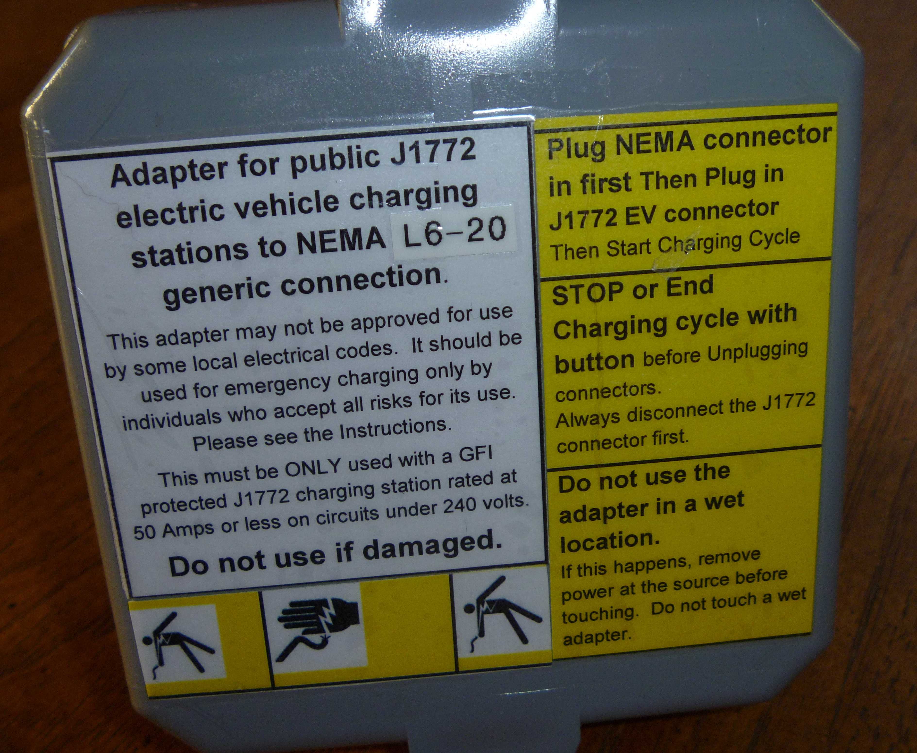
x - Warning labels - modularevpower.com (I asked and they were nice enough to include them in the shipment of the J1772)
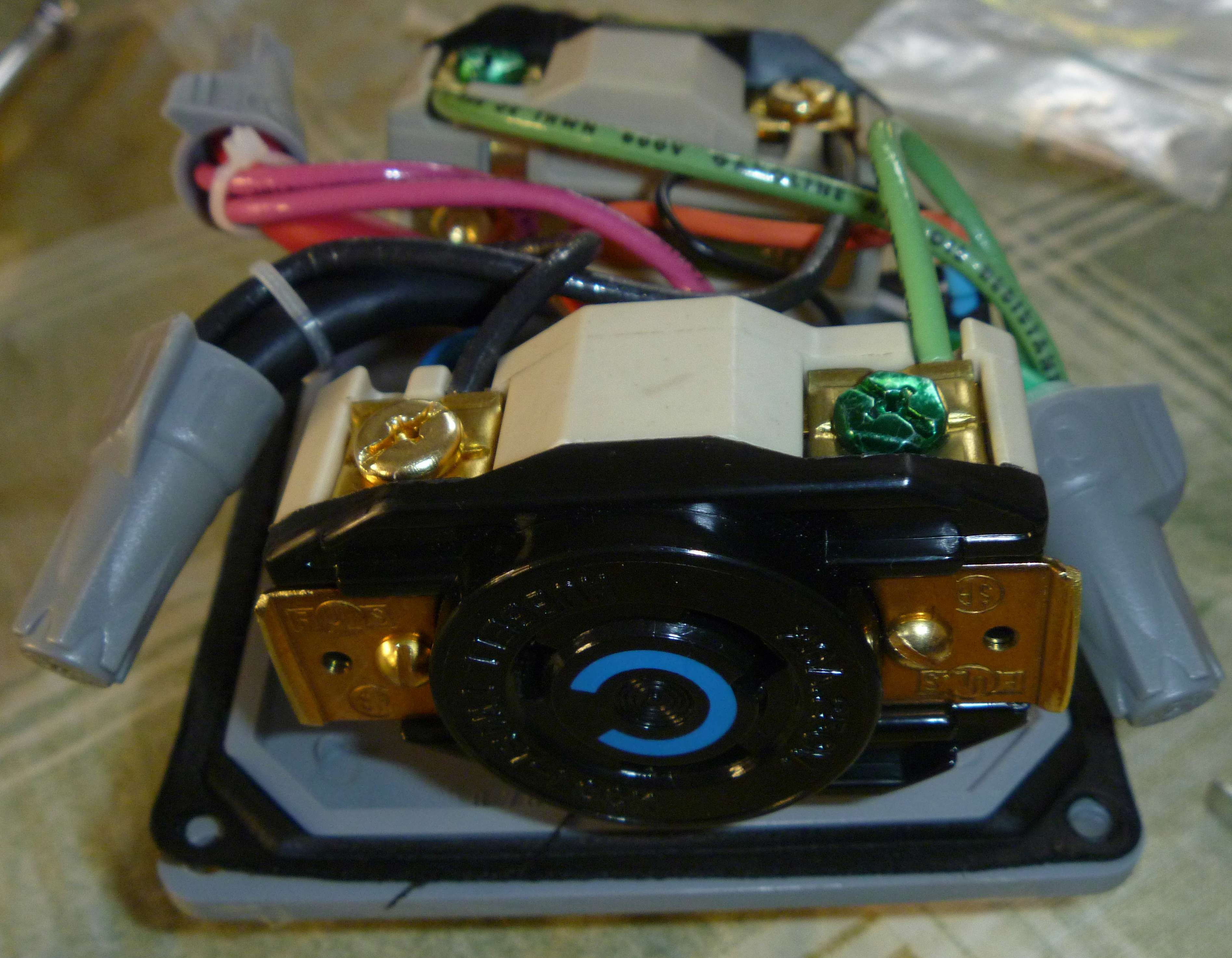
2- L6-20 Receptacles - Most hardware stores have these. I got mine on ebay. Good price but defective and needed to be fixed (see previous post, they were Hubbell HBL2320 batch code VKJ stamped near screw hole one side)
3- 18-6 AWG Wire Nuts - Ace hardware comes three to a package which is all I needed. Need to be rated for one #6 and two #12 wires.
1- SPST Switch - Fry's, Radio Shack, Hardware store
1- Diode (1N4001-1N4007) - Electronics store. You can use the 1N4001 but I had lots of 1N4007 so I used it. Just higher working voltage so any of these will work.
3- 12 gauge stranded wire, 12" each of Red, Black, Green - Electronics/Hardware store
1 -Resistor 2.7K ohms 1/4w - Electronics store
1- Resistor 1.3K ohms 1/4w - Electronics store
3- Small cable ties - Hardware store
x - Heat shrink tubing - Electronics/Hardware stores

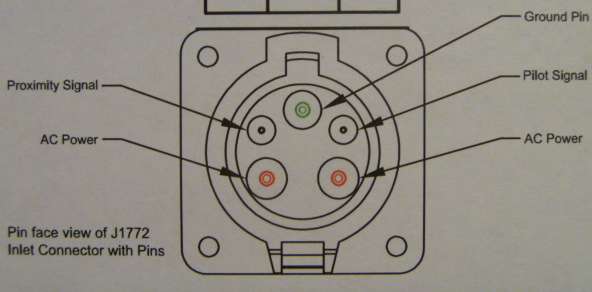
Here is the J1772 pinout. (added per Tony's request)
j1772.jpg


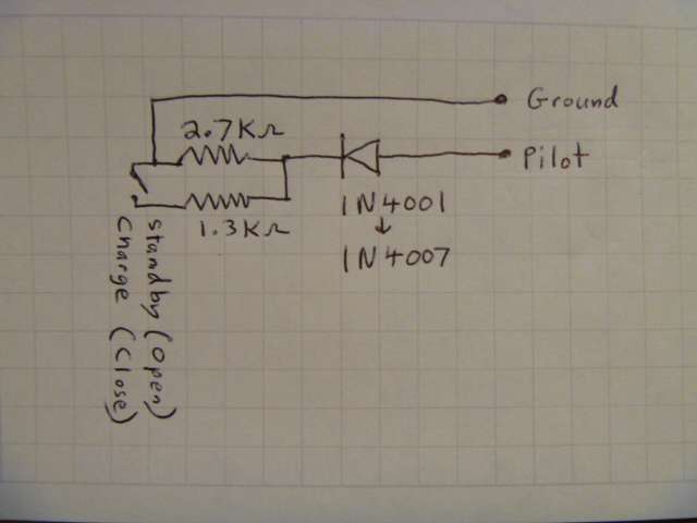
Here is the diagram of the Pilot termination circuit.
pilotcircuit.jpg

The Ground and Pilot signals come from the J1772 inlet. I used several layers of heat shrink tubing to insulate the Diode, Resistors and Switch.

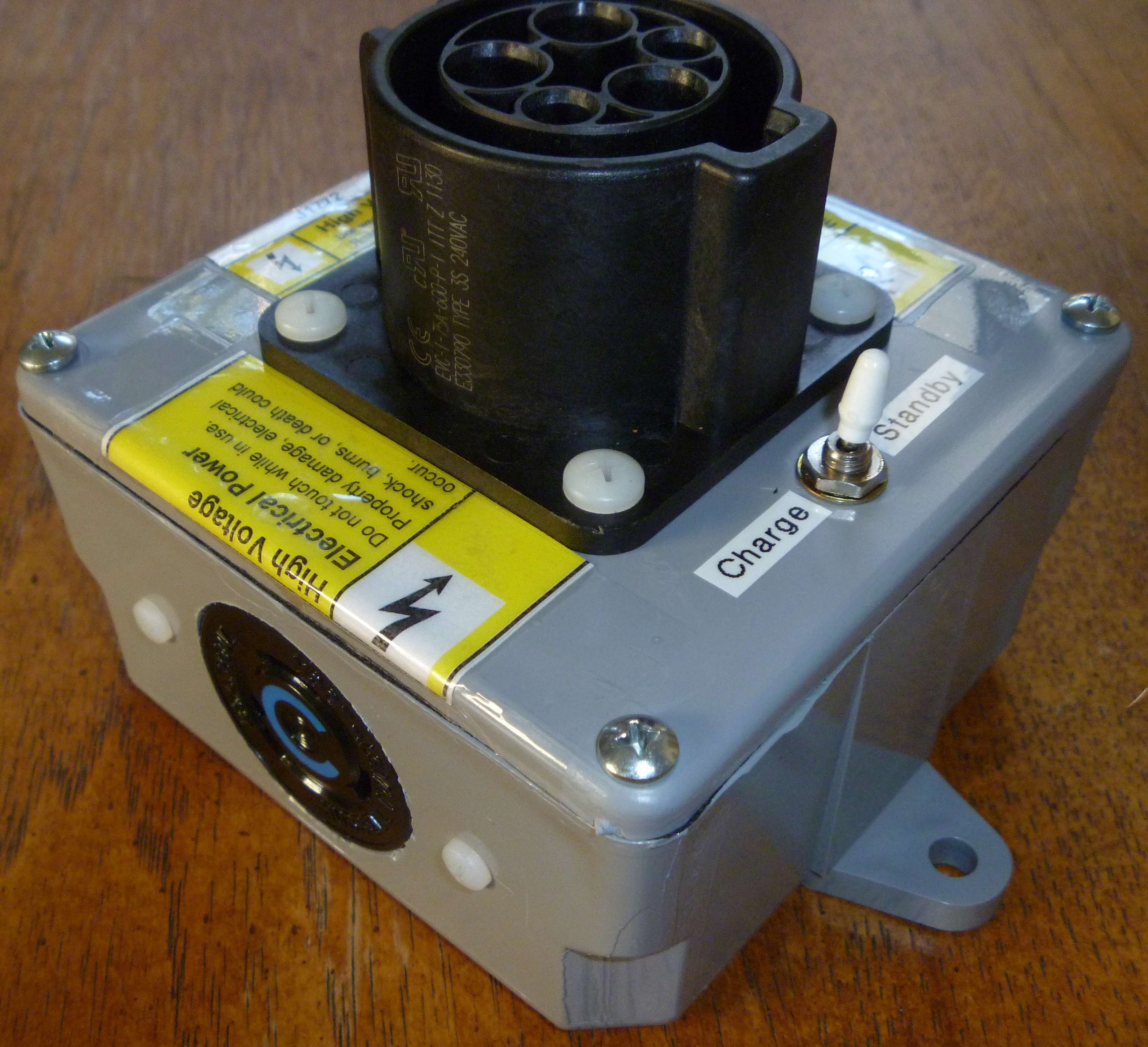
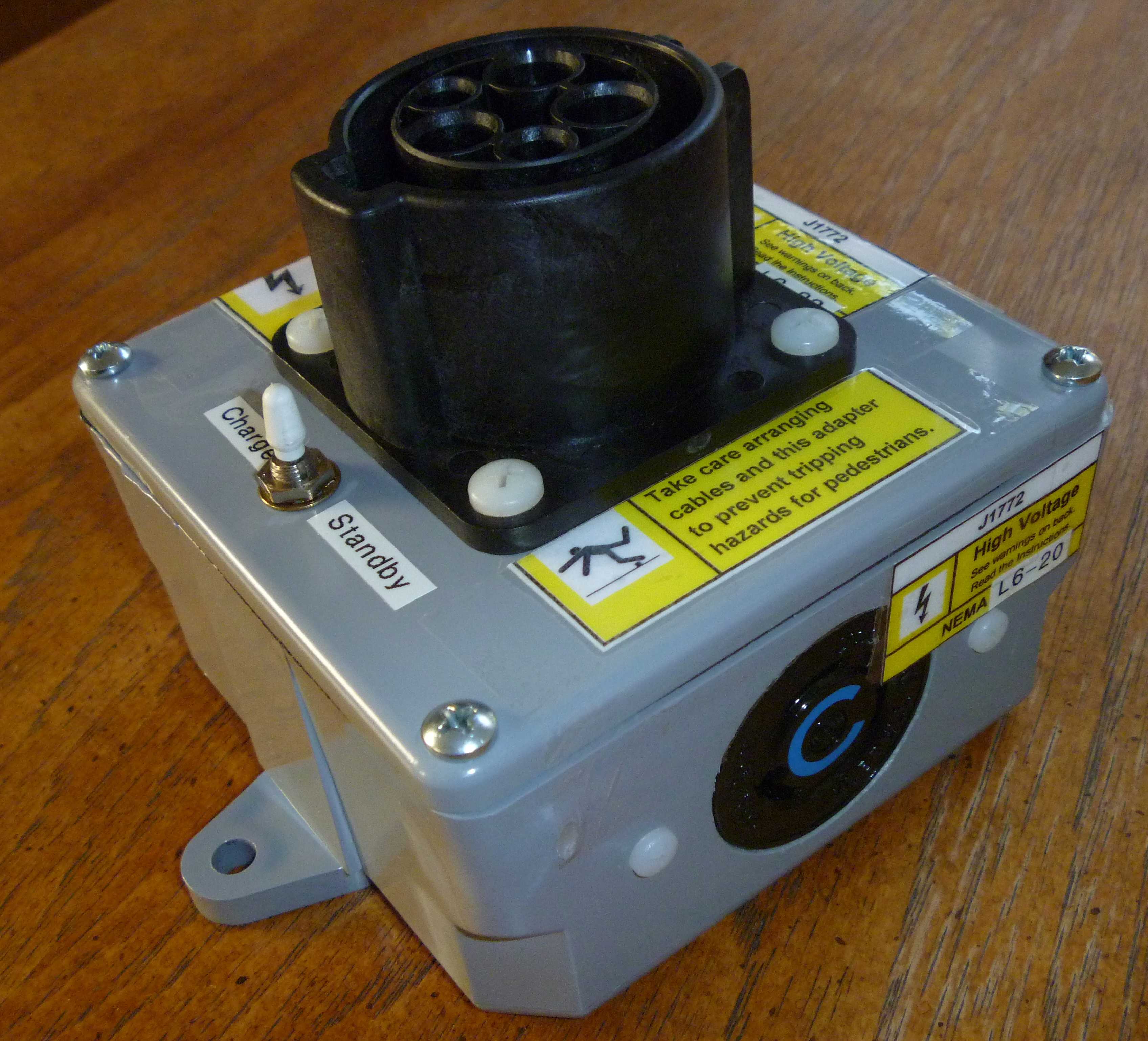
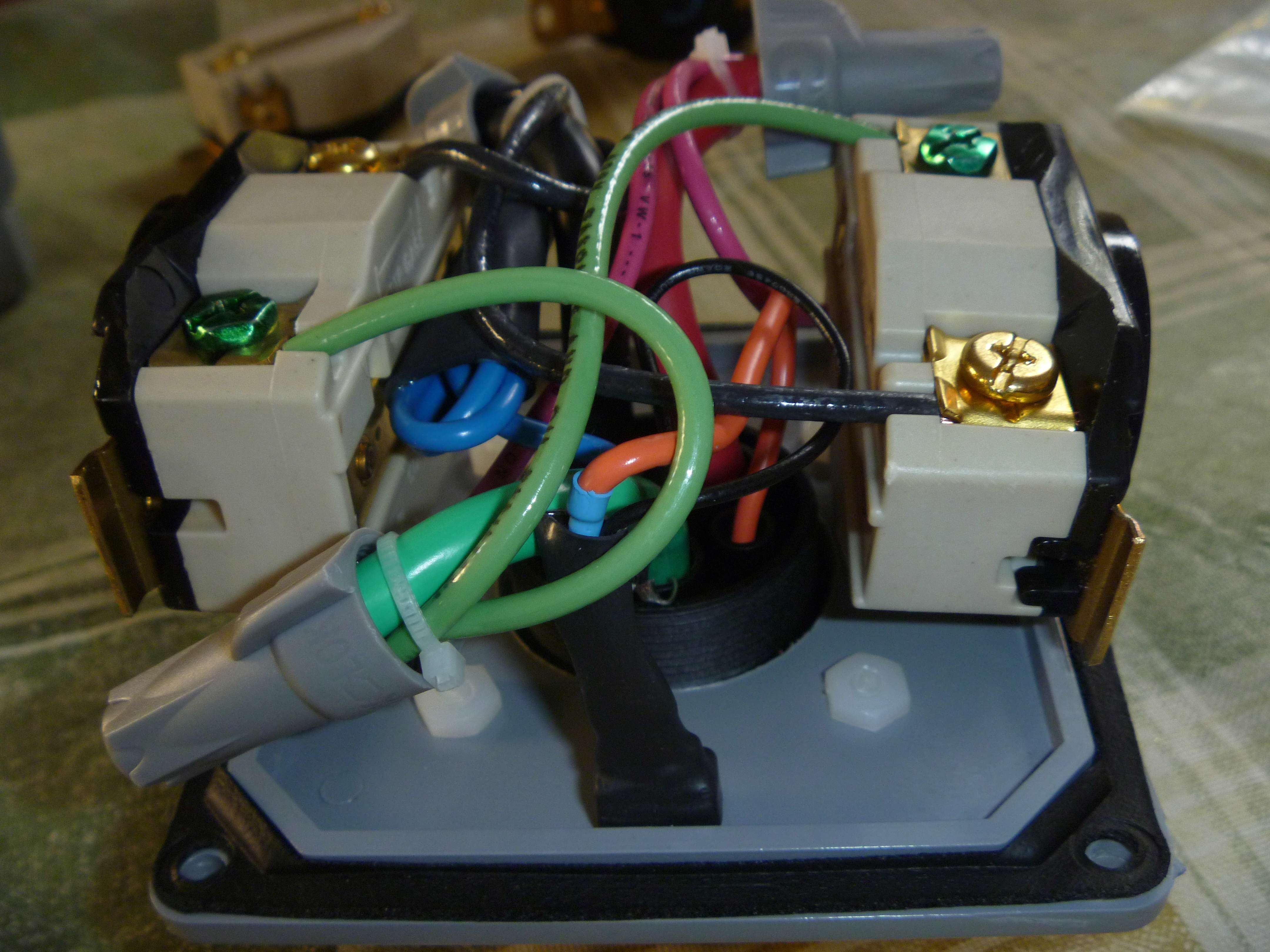
Here is the completed Pilot logic all in a black wrap. Orange wire is the Pilot and the thin black wire in the background is ground. (Blue wire is unused Proximity Signal)
switchwiring.jpg


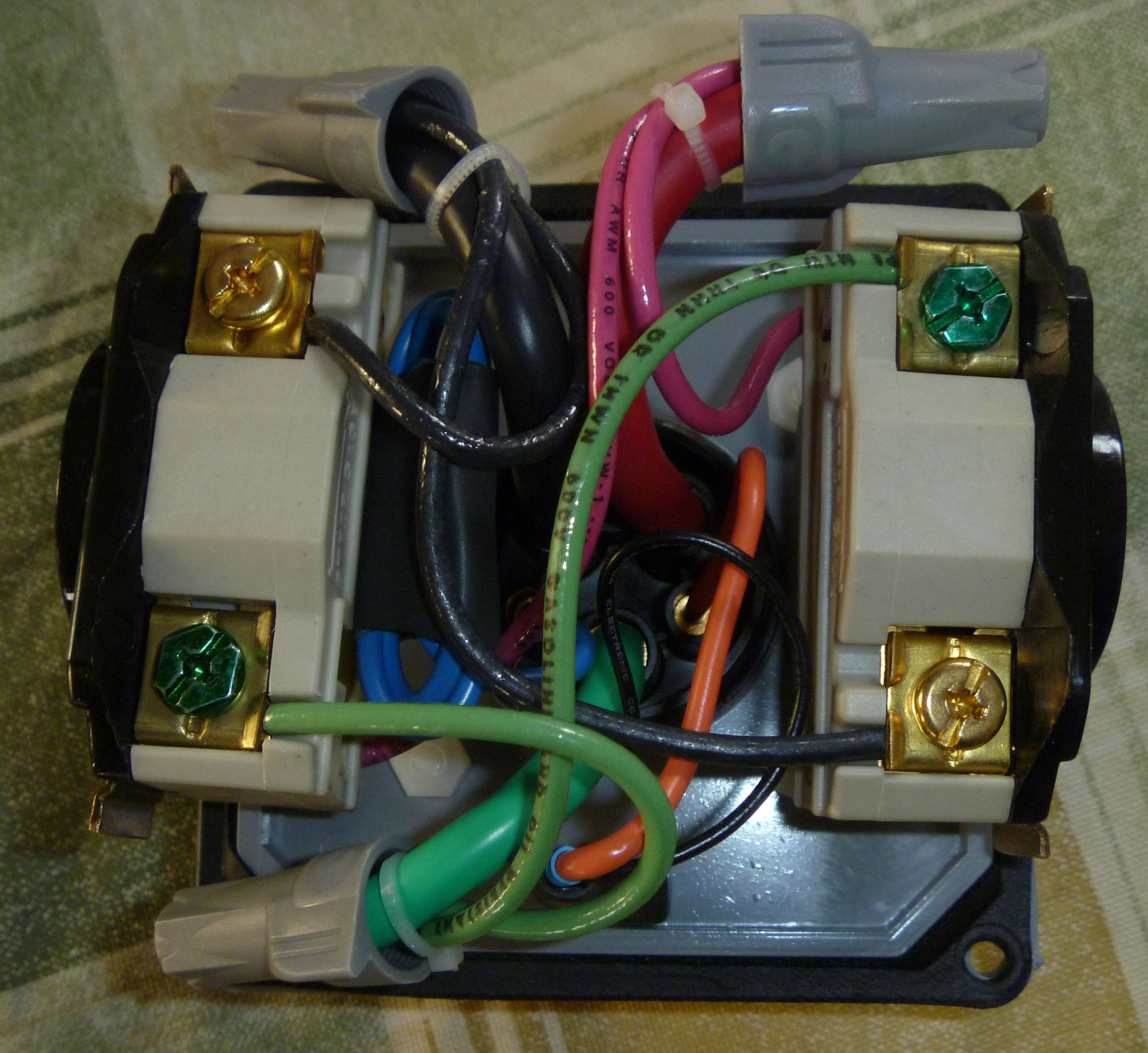
Here is a top view. Note the cable ties used to hold the three wires together and aligned so the wire nut can be twisted on and it also reduces the chance any wire will come loose and short out. Each wire nut is in a separate corner and when closing the box the three wires are forced into each wire nut.
wiringtop.jpg


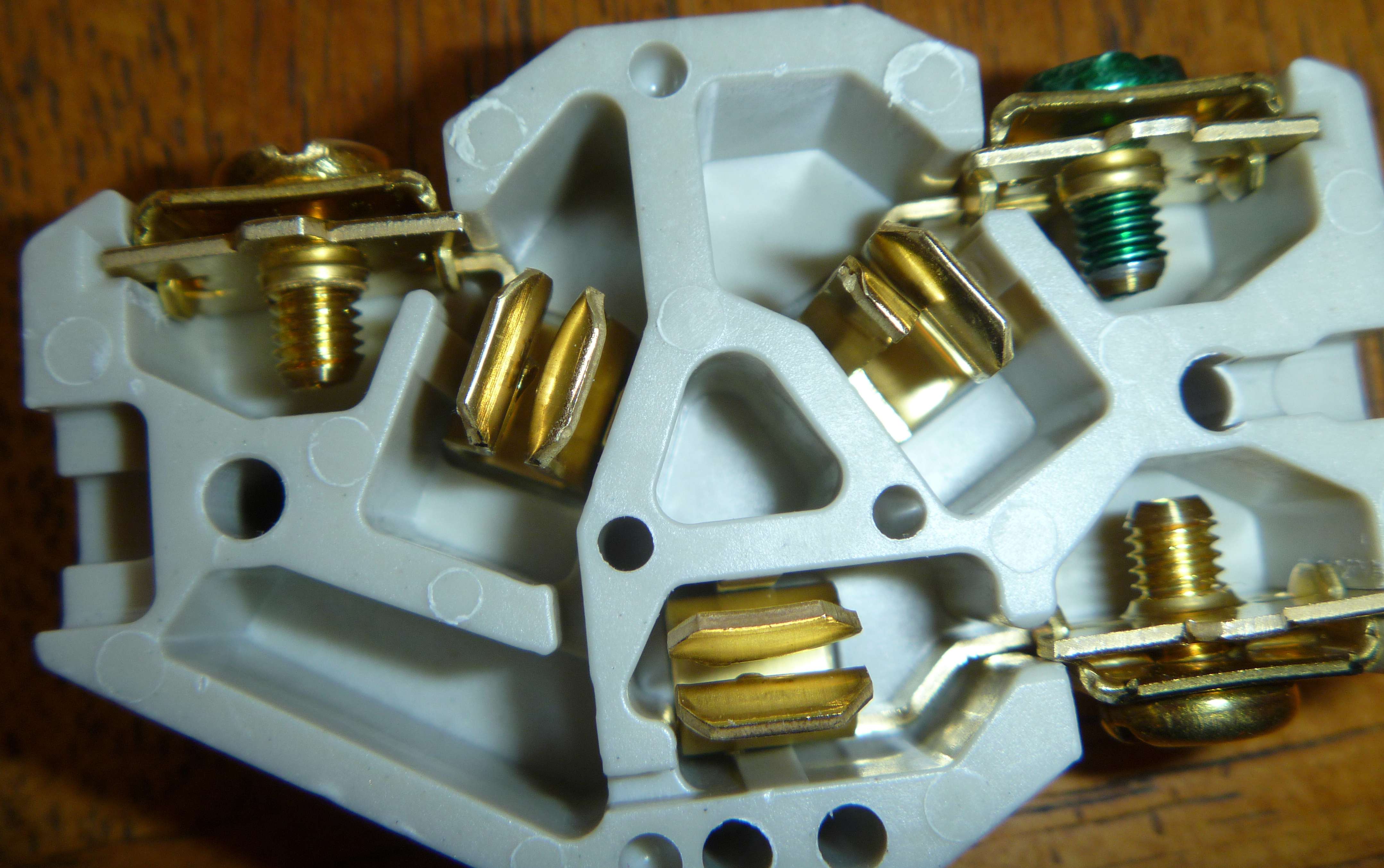
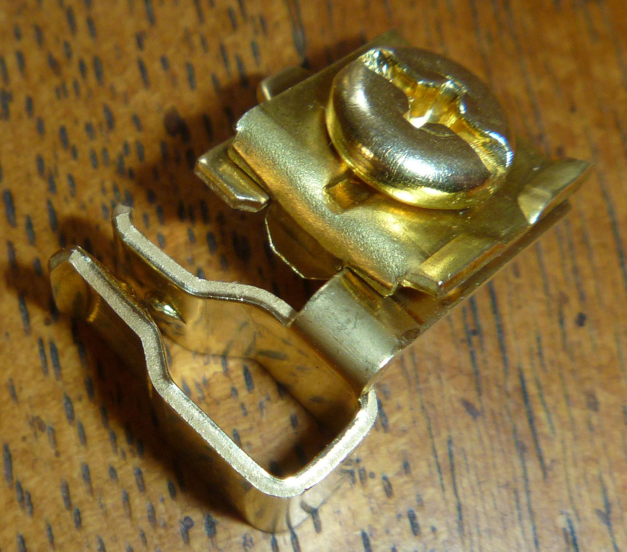
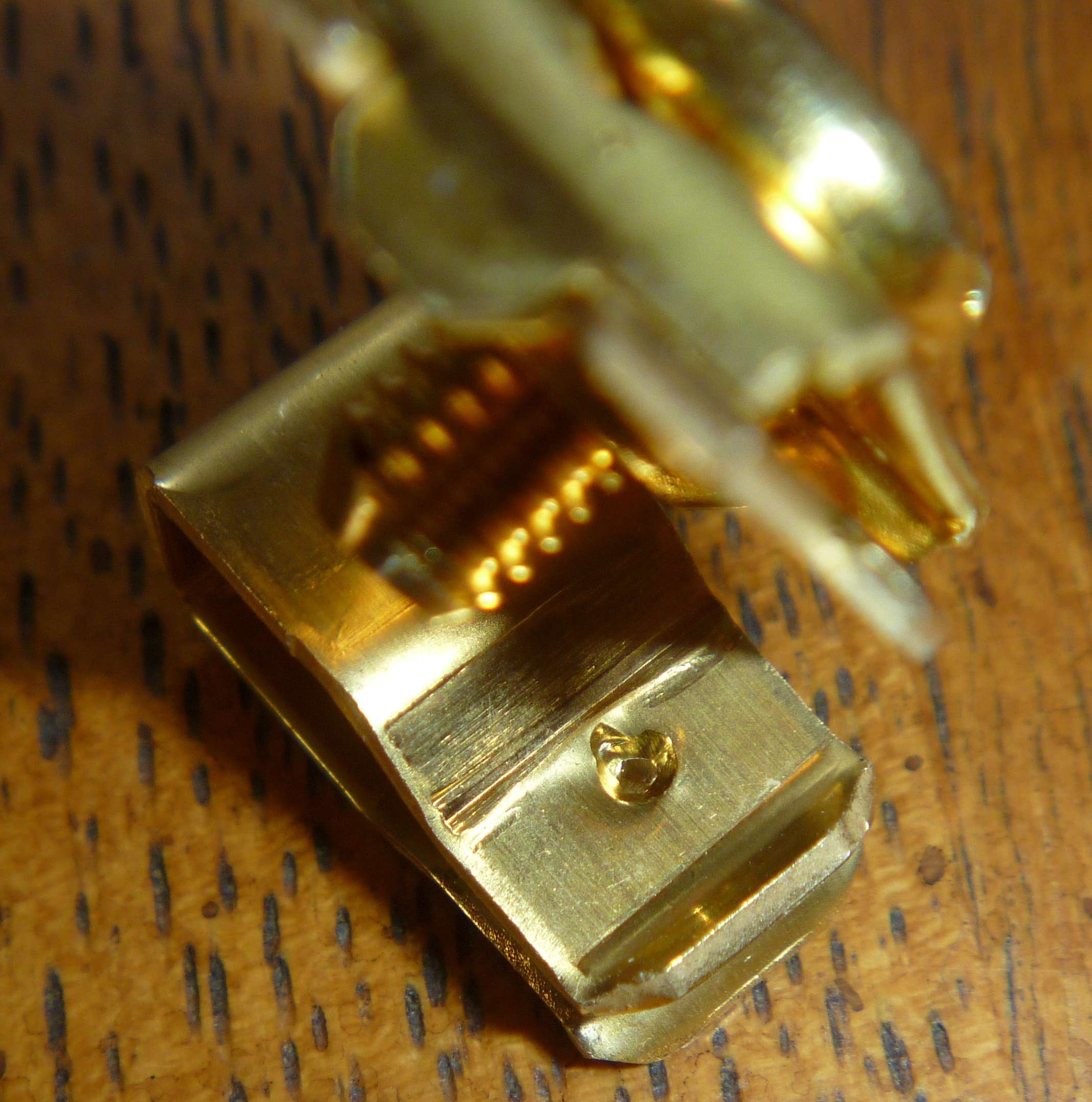
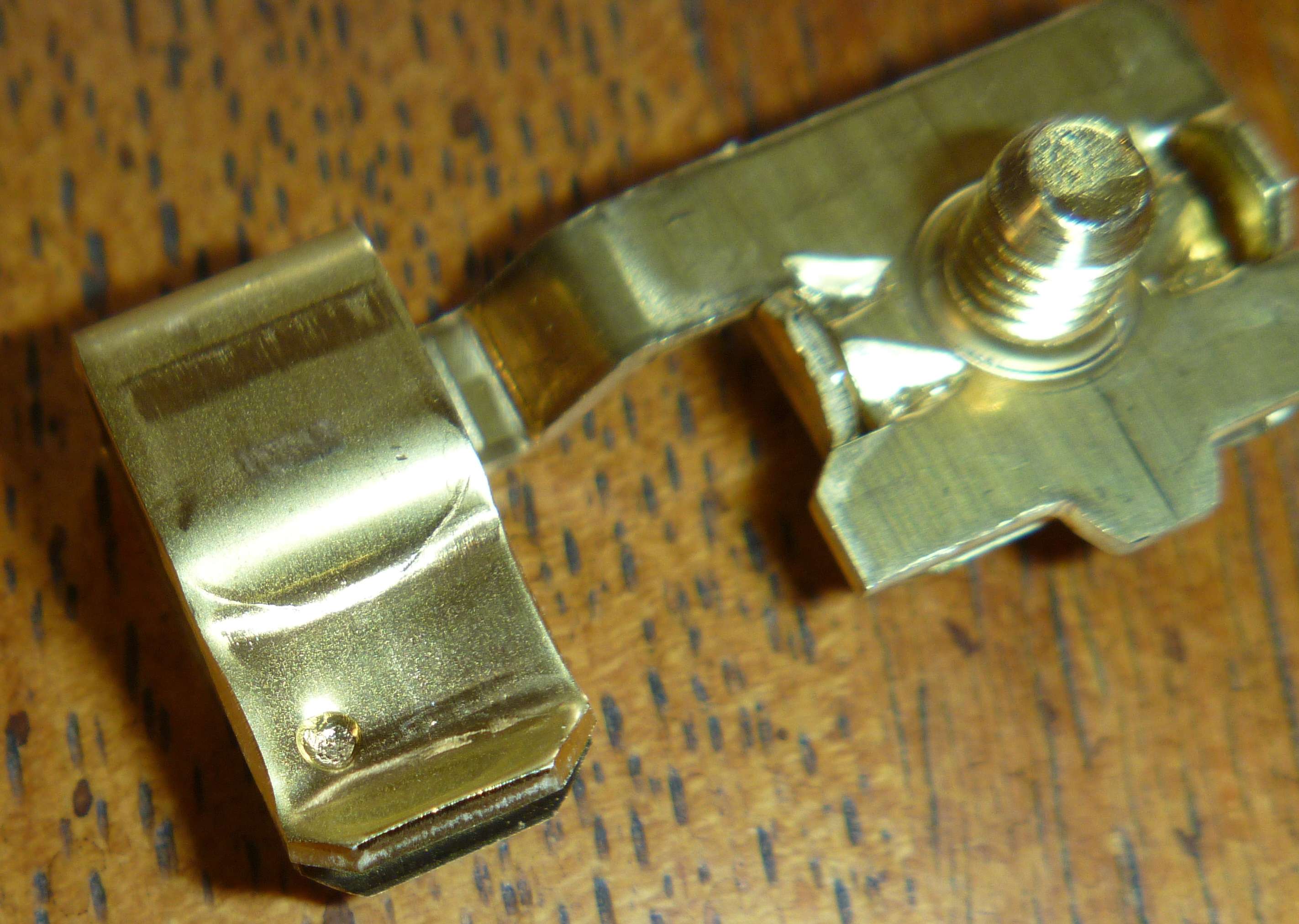
In this picture of the L6-20 you can see the screws I used to replace the long rivets I drilled out to correct the bad contact problem. Batch code was on the end I cut off to make the receptacle fit the box.
l620view.jpg


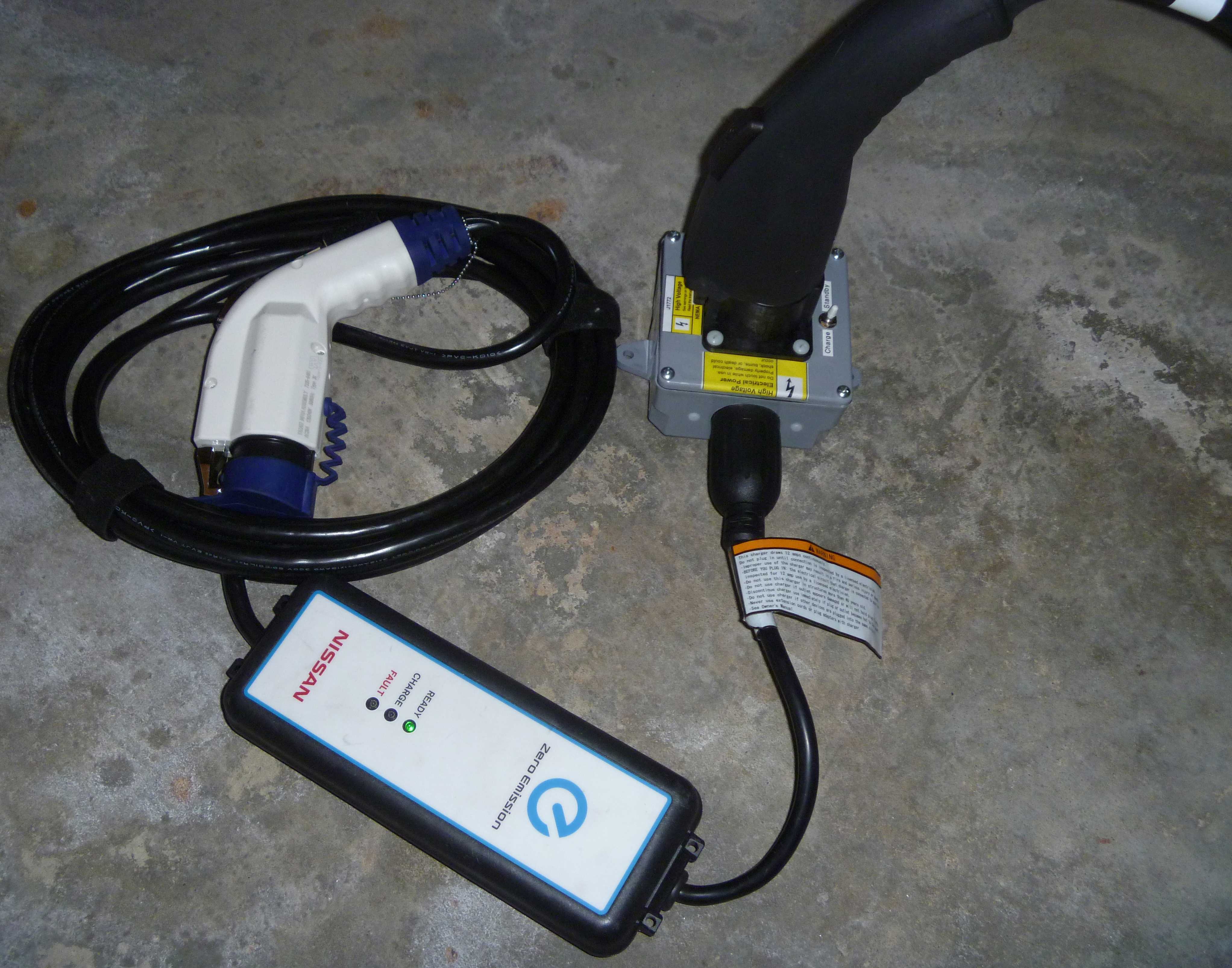
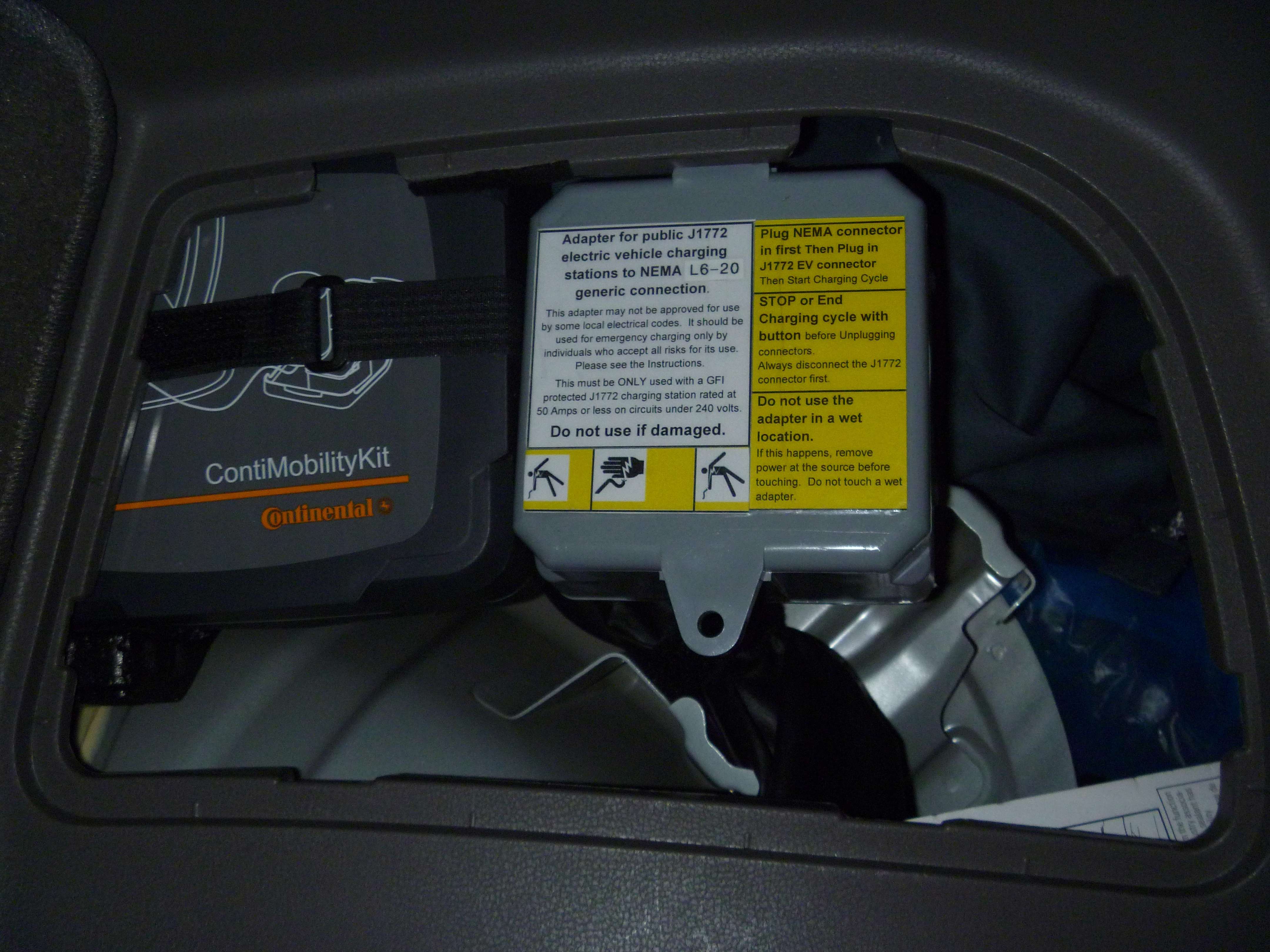
Here is where I store the adapter. I also have a tire repair kit (upper right corner), 25' L6-20 12 guage extension (shiny blue plastic bag at top, extra adapters in blue cloth bag (6-20,6-50,14-30/50/60,CS6365), and multi meter. You can get a lot in there (just added L14-20 & L14-30 adapters and it still all fits in there).
storaget.jpg


Jim
 
Awesome report. I think I'll make one! I don't see where there is a diagram to show which pin is the pilot pin, etc.

Oh, if anybody is interested, I have 3 of the Nissan charge port covers coming from Japan. Not cheap! Let me know if you want one:

TonyWilliams
at
LoveMyLEAF
dot
Com

dop_th_06.jpg
 
Ingineer said:
I use two Rev1 units when I do it, which is 24A total. 32A is pushing it!

Which components are of most concern regarding being pushed? Wiring and connections in the wall mounted L2 EVSE?

I tangentially witnessed both a residential Blink and a residential Chargepoint split to feed two 16A EVSE upgraded portable units (32A total on nominally 30A wall units). It may have been pushing it, but neither one attempted any self protection at that current level. This test happened at the last BayLeaf seat heater install part, a week ago.

Howdy Goudey
 
A 30a (or 32a) EVSE is going to be on a 40A circuit. You won't trip the breaker. I suppose the wire gauge in the "e-hose" might be of concern - so just don't coil it up!
 
hgoudey,

You misunderstood what Ingineer (Phil) and I were talking about. It was not the source ESVE (Blink, Chargepoint,...) but his use of 12 gauge wire downstream to carry 32 amps (2 Rev 2 16 Leaf ESVE units).

Phil's Y splitter (which is only 12 guage) would need to be at least 10 guage before it splits into two lines since it would be carrying 32 amps. Also his connectors were only L6-20s but that is probably less of a concern.

For this reason Phil said he limited his use of his Y cable setup to two Rev 1 units at 12 amps each so only 4 amps over the 20 amp wire limit. So it will get warmer than normal.

Jim
 
Turbo3 said:
hgoudey,

You misunderstood what Ingineer (Phil) and I were talking about. It was not the source ESVE (Blink, Chargepoint,...) but his use of 12 gauge wire downstream to carry 32 amps (2 Rev 2 16 Leaf ESVE units).

Phil's Y splitter (which is only 12 guage) would need to be at least 10 guage before it splits into two lines since it would be carrying 32 amps. Also his connectors were only L6-20s but that is probably less of a concern.

For this reason Phil said he limited his use of his Y cable setup to two Rev 1 units at 12 amps each so only 4 amps over the 20 amp wire limit. So it will get warmer than normal.

Jim


i think Phil stated the "24 amp" option was for use on a 30 amp circuit.
 

Latest posts

Back
Top