
You are using an out of date browser. It may not display this or other websites correctly.
You should upgrade or use an alternative browser.
You should upgrade or use an alternative browser.
SAE J1772 inlet port Dimensions
- Thread starter dzd
- Start date
Help Support My Nissan Leaf Forum:
This site may earn a commission from merchant affiliate
links, including eBay, Amazon, and others.
davewill
Well-known member
I couldn't find a a side view, but these might help.
Not perfect but here's one drawing:

And here's more detail: http://www.fveaa.org/fb/FCI_Power-S3-SAE-J1772-Charge-plug-2010-06_276.pdf" onclick="window.open(this.href);return false;

Not perfect but here's one drawing:
And here's more detail: http://www.fveaa.org/fb/FCI_Power-S3-SAE-J1772-Charge-plug-2010-06_276.pdf" onclick="window.open(this.href);return false;
I have the same idea. Earlier today, I searched the Autodesk 123D gallery for similar design, but found nothing.
The free 123D software is so fun and easy to use, you will have it done in no time. Might be nice to add a momentary switch to sense the J plug being docked (in case of future OpenEVSE functionality).
Did you find out what a local fabricator might charge once you finalize your design?
The free 123D software is so fun and easy to use, you will have it done in no time. Might be nice to add a momentary switch to sense the J plug being docked (in case of future OpenEVSE functionality).
Did you find out what a local fabricator might charge once you finalize your design?
borland said:I have the same idea. Earlier today, I searched the Autodesk 123D gallery for similar design, but found nothing.
The free 123D software is so fun and easy to use, you will have it done in no time. Might be nice to add a momentary switch to sense the J plug being docked (in case of future OpenEVSE functionality).
Did you find out what a local fabricator might charge once you finalize your design?
I found the auto desk free software to be problematic. It doesn't tend to work if their predefined shapes don't fit together. I really wish pro engineer had a free version. That software is really nice. I'll continue to try the free stuff.
Thanks for the drawing good find. I'll have to also take some measurements to get the top latch right.


garygid
Well-known member
Nice work.
The cost depends upon the type and amount of material used in the part.
Perhaps make thinner walls, and add gussets at stress points.
Complexity is not very important, so things like a thin wall
with ribs for strength can save money.
One of our members used http://www.shapeways.com" onclick="window.open(this.href);return false; recently
to make the "cage" (enclosure) for his CANary project.
Subject: The CANary project
garygid
Well-known member
For safety, you might want to round all the exterior edges.
garygid
Well-known member
If the latch "bump" on the top is a bit too high, you will
be able to push the J1772 in, but not be able to get it out!
be able to push the J1772 in, but not be able to get it out!
garygid
Well-known member
The poor man's version uses these PVC fittings:
(of course, you wanted much nicer)
A Cap (or floor flange) that can be screwed to the wall,
a Short piece of pipe to connect to the elbow,
a 45 degree elbow, possibly with another short
piece for pipe... all sized to "fit" the J1772 plug.
(of course, you wanted much nicer)
A Cap (or floor flange) that can be screwed to the wall,
a Short piece of pipe to connect to the elbow,
a 45 degree elbow, possibly with another short
piece for pipe... all sized to "fit" the J1772 plug.
garygid
Well-known member
Smidgen,
Where are you located?
It is most likely that we could arrange for a test fitting.
I would check the clearances before printing, to make
sure that any surface "roughness" (variations) will
not interfere with the fit of the J1772 plug.
What kind of 3D printer do you have available?
What material do you use with it?
Smidge204 said:How big is it? I might give it a go in my printer just for laughs.
Though I don't have any connector to test fit with.
=Smidge=
It's actually smaller than it appears in the sketch.
base is: 70 mm x 65 mm x 5 mm thick
tube is: 5 mm thick x 50 mm O.D.
overall height is: 70 mm
PM me if you want the STL file. Dimensionally, it is correct, but I'd need to do some additional QC checks before releasing the file.
garygid said:Smidgen,
Where are you located?
It is most likely that we could arrange for a test fitting.
I would check the clearances before printing, to make
sure that any surface "roughness" (variations) will
not interfere with the fit of the J1772 plug.
What kind of 3D printer do you have available?
What material do you use with it?
Long Island, NY
I use a FDM type printer running PLA (poly-lactic acid). It's a biodegradable plastic with a low glass temperature (~60C/140F) not terribly suited for hot things
") Not sure how it's survive being exposed to the elements but it makes for some nice mechanical bits.
Not sure how it's survive being exposed to the elements but it makes for some nice mechanical bits.Here's an up-close picture of what the finished print surface looks like. By default I print with 0.25mm layers so that's the height of the ridged you see there... I don't think that kind of roughness will be a problem.
=Smidge=
nosuchthing
Well-known member
- Joined
- Jul 16, 2010
- Messages
- 740
I made this before I even got my Leaf in 2011. Have been using it ever since. Got one request to make one from England (of all places).
dzd said:nice job Borland!!! if the fit is good would you make the file available or put it on file with shapeways so we can all partake?
Looks like Smidge did a great job on printing the part. The short video is is very impressive too.
As soon as the part arrives, I'll post a photo showing the fitup with my J-plug.
Smidge makes it look much easier than it is to print. The drawing can be dimensionally correct, but depending on how well the 3D printer is calibrated, the part can come out a different size. There are other printing factors that affect sizing too.
Smidge said that his printing software estimated the cost of PLA filament to be $2. I'm not sure what Shapeways charges for a part this size or how accurate their printers are. Something I need to inquire about (cost and quality).
If this part is going to be widely made, I'd like to add a freeze protection cover above the latch so the part could be used outdoors.
Thank you Smidge204!
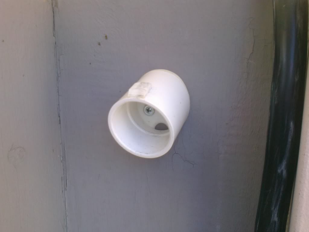
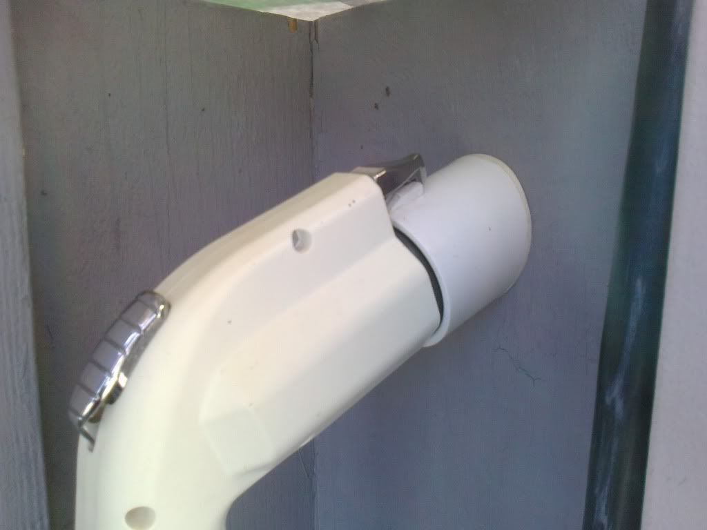
The part arrived in the mail today. Looks great. Fitup with the J-plug is good; plug snaps in place with no interferences. The screw hole sizes and screwdriver access are good also.
Here's some photos showing fitup with my J1772 plug (manufactured by ITT)....you can see that the part was printed with honeycomb infill...


If mounted to a wall, the J-plug handle points straight down.


You can see in this photo, it's not a tight fit. Printing tolerances make this difficult to size precisely.

My J1772 has a foam gasket seal around the outside of the plug. When connected with the part, the gasket is barely compressed. Not sure if other J-plug have this feature.
Haven't done any destructive testing, but the part looks to be strong enough. Only design change I'd make, is to shorten the tube by a few milimeters.
The part arrived in the mail today. Looks great. Fitup with the J-plug is good; plug snaps in place with no interferences. The screw hole sizes and screwdriver access are good also.
Here's some photos showing fitup with my J1772 plug (manufactured by ITT)....you can see that the part was printed with honeycomb infill...
If mounted to a wall, the J-plug handle points straight down.
You can see in this photo, it's not a tight fit. Printing tolerances make this difficult to size precisely.
My J1772 has a foam gasket seal around the outside of the plug. When connected with the part, the gasket is barely compressed. Not sure if other J-plug have this feature.
Haven't done any destructive testing, but the part looks to be strong enough. Only design change I'd make, is to shorten the tube by a few milimeters.
TonyWilliams
Well-known member
borland said:Haven't done any destructive testing, but the part looks to be strong enough. Only design change I'd make, is to shorten the tube by a few milimeters.
I'd put a gusset underneath the assembly and lower the two bottom mounting bolts a few inches.
nosuchthing
Well-known member
- Joined
- Jul 16, 2010
- Messages
- 740
How about making a mold out of it and proceed from there... I like it!
Similar threads
- Replies
- 4
- Views
- 1K
- Replies
- 2
- Views
- 649